16 TB MRI1 09.00 E
4.6 Determining earth short-circuit
fault direction
The SR-relay type is used in solidly-earthed or resis-
tance-earthed systems for determining earth short-circuit
fault direction. The measuring principle for determining
the direction is based on phase angle measurement
and therefore also on the coincidence-time measure-
ment between earth current and zero sequence volt-
age.
The zero sequence voltage U
0
required for determining
the earth short-circuit fault direction is generated inter-
nally in the secondary circuit of the voltage transform-
ers.
With SR/ISR-relay types the zero sequence voltage U
0
can be measured directly at the open delta winding
(e-n). Connection A3/A2.
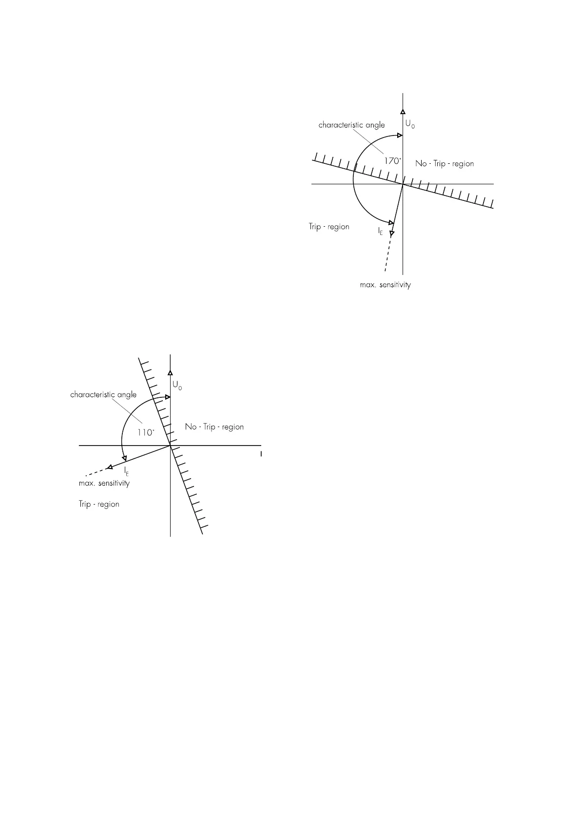
Most faults in a characteristic angle are predominantly
inductive in character. The characteristic angle be-
tween current and voltage at which the greatest meas-
uring sensitivity is achieved has therefore been se-
lected to precede zero sequence voltage U
0
by 110°.
Figure 4.8: Characteristic angle in solidly earthed-systems (SOLI)
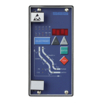
Most faults in a resistance-earthed system are pre-
dominantly ohmic in character, with a small inductive
part. The characteristic angle for these types of system
has therefore been set at +170° in relation to the zero
sequence voltage U
0
(see Figure 4.9).
Figure 4.9: Characteristic angle in resistance-earthed systems (RESI)
The pickup range of the directional element is set by
turning the current indicator at the characteristic angle
through + 90°, to ensure reliable determination of the
direction.
4.7 Demand imposed on the main
current transformers
The current transformers have to be rated in such a
way, that a saturation should not occur within the fol-
lowing operating current ranges:
Independent time overcurrent function: K1 = 2
Inverse time overcurrent function: K1 = 20
High-set function: K1 = 1.2 - 1.5
K1 = Current factor related to set value
Moreover, the current transformers have to be rated
according to the maximum expected short circuit cur-
rent in the network or in the protected objects.
The low power consumption in the current circuit of
MRI1, namely <0,2 VA, has a positive effect on the
selection of current transformers. It implies that, if an
electromechanical relay is replaced by MRI1, a high
accuracy limit factor is automatically obtained by us-
ing the same current transformer.
 Loading...