TD_MRI1_06.05_GB 17
5 Operation and setting
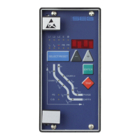
5.1 Display
Function Display shows Pressed push button Corresponding LED
Normal operation SEG
Measured operating values Actual measured values,
(related to I
N
; U
E
1)
)
(XR-type related to % I
N
)
<SELECT/RESET>
one time for each
L1, L2, L3, E, U
E>
, I
E>
Measuring range overflow max. <SELECT/RESET> L1, L2, L3, E
Setting values:
phase (I>; CHAR I>; t
I>
; I>>; t
I>>
)
earth (I
E>
; CHAR I
E
; t
IE>
; I
E>>
; t
IE>>
; U
E>
)
Current settings
Trip delay
Characteristics
<SELECT/RESET>
one time for each
parameter
I >; CHAR I>; t
I>
; I>>;
t
I>>
; LED →←
I
E>
;CHAR I
E
; t
IE>
;I
E>>
;
t
IE>>
;U
E>
Reset setting (only available at inverse
time characteristics)
0s / 60s <SELECT/RESET>
<+><->
I>; CHAR I>; t
I>
I
E>
; CHAR I
E>
; t
IE>
Relay characteristic angle for pase cur-
rent directional feature
RCA in degree (°) <SELECT/RESET>
<+><->
LED →← (green)
Warning reverse direction
1)
no warning
warning
NOWA
WBAK
<SELECT/RESET>
LED →← (red) + I>
LED →← (red) + I
E>
Warning or Trip at earth fault
measuring (E- and ER/XR-types)
TRIP
WARN
<SELECT/RESET>
<+><->
I
E>
Measured method of the residual
voltage U
E
1)
3 PHA ; E-N ; 1:1 <SELECT/RESET>
<+><->
U
E>
residual voltage setting voltage in volts <SELECT/RESET><+><-> U
E>
changeover of isolated (sin ϕ)
or compensated (cos ϕ)
networks (for ER/XR-type)
SIN
COS
<SELECT/RESET>
<+><->
Change over of solidly/resistance
earthed networks (SR-type)
SOLI
RESI
<SELECT/RESET>
<+><->
Switch failure protection tCBFP <SELECT/RESET> <+><->
Tripping protection
switch failure protection
CBFP After fault tripping
Nominal frequency f=50 / f=60 <SELECT/RESET><+><->
Switch-over LED flash
No LED flash
FLSH
NOFL
<SELECT/RESET>
<+><->
Blocking of function EXIT <+> until max. setting value LED of blocked
parameter
Slave address of serial interface 1 - 32 <SELECT/RESET>
<+><->
RS
Baud-Rate
2)
1200-9600 <SELECT/RESET> <+><-> RS
Parity-Check even odd no <SELECT/RESET> <+><-> RS
Recorded fault data Tripping currents and other
fault data
<SELECT/RESET>
one time for each phase
L1, L2, L3, E
I>, I>>, I
E>
, I
E>>
, U
E>
Save parameter? SAV? <ENTER>
Delete failure memory wait <-> <SELECT/RESET>
Enquiry failure memory FLT1; FLT2..... <-><+> L1, L2, L3, E
I>, I>>, I
E>
, I
E>>
,
Save parameter! SAV! <ENTER> for about 3 s
Software version First part (e.g. D01-)
Sec. part (e.g. 8.00)
<TRIP>
one time for each part
Manual trip TRI? <TRIP> three times
Inquire password PSW? <TRIP><ENTER>
Relay tripped TRIP <TRIP>
or after fault tripping
Secret password input XXXX <SELECT/RESET>
<+><-><ENTER>
System reset SEG <SELECT/RESET>
for about 3 s
Table 5.1: possible indication messages on the display
1)
refer to 4.4
2)
only Modbus
 Loading...