28 TD_MRI1_06.05_GB
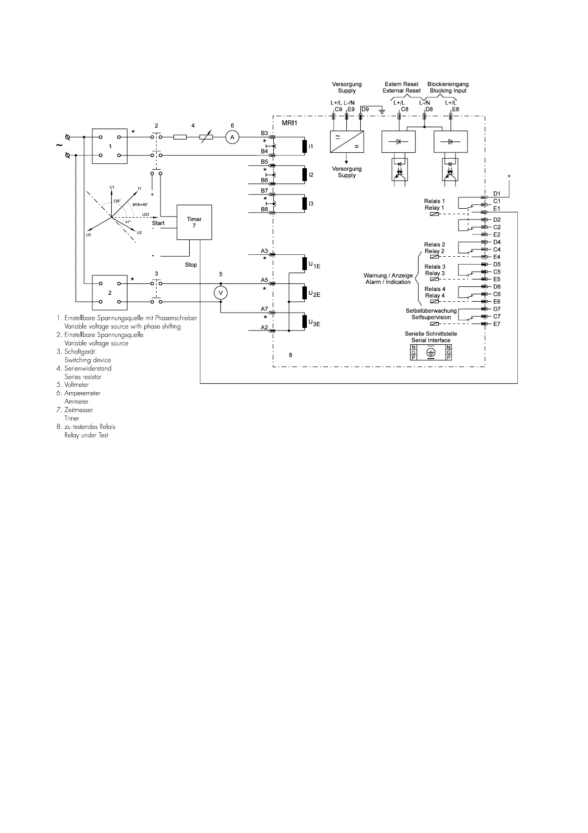
6.4.7 Example of a test circuit for MRI1
relay with directional feature
Figure 6.2: Test circuit
For testing relays with directional feature, current and
voltage input signals with adjustable phase shifting are
required. Figure 6.2 shows an example of a single
phase test circuit with adjustable voltage and current
energizing the MRI1 relay under test.
For testing a relay with directional feature, one of the
input energizing quantity (voltage) shall be applied to
the relay with a constant value within its effective
range. The other input energizing quantity (current)
and phase angle shall be appropriately varied.
MRI1 is a three phase directional time overcurrent re-
lay with relay connection angle of 0°. The relay input
currents and their corresponding reference voltages are
shown in the following table (refer to 4.3):
If the single phase test circuit as illustrated in
Figure 6.2 is applied to test the directional feature of
the relay and the current source is connected to
phase 1 current input (B3/B4), then the voltage source
should be connected to relay terminals A5/A7.
In order to test the directional feature, all activation
points should first be set to “EXIT”. Then a test voltage
equivalent to the rated voltage is connected to termi-
nals A5/A7 and a current of 1 x In is impressed upon
the current inputs B3/B4.
It is now possible to read and check all measured val-
ues in accordance with Table 6.1. If the phase posi-
tion is changed, the values I
Q
and I
P
change. If the an-
gle is changed by 90
o
, for example, the measured va-
lue for current input I1 must be 1.0 for I
P
and +/- 0.0
for I
Q
.
Determining the change in direction
The angle of greatest sensitivity for determining the
phase direction is adjustable between 15
o
and 83
o
.
Consequently, the greatest sensitivity is achieved with
setting 49
o
if the input current leads the input voltage
by 49
o
. This setting results in a tripping range in ad-
vance direction of 139
o
leading to 41
o
lagging if the
marginal regions are neglected on account of lack in
measuring precision.


 To Next Page
 Loading...