TD_MRI1_06.05_GB 29
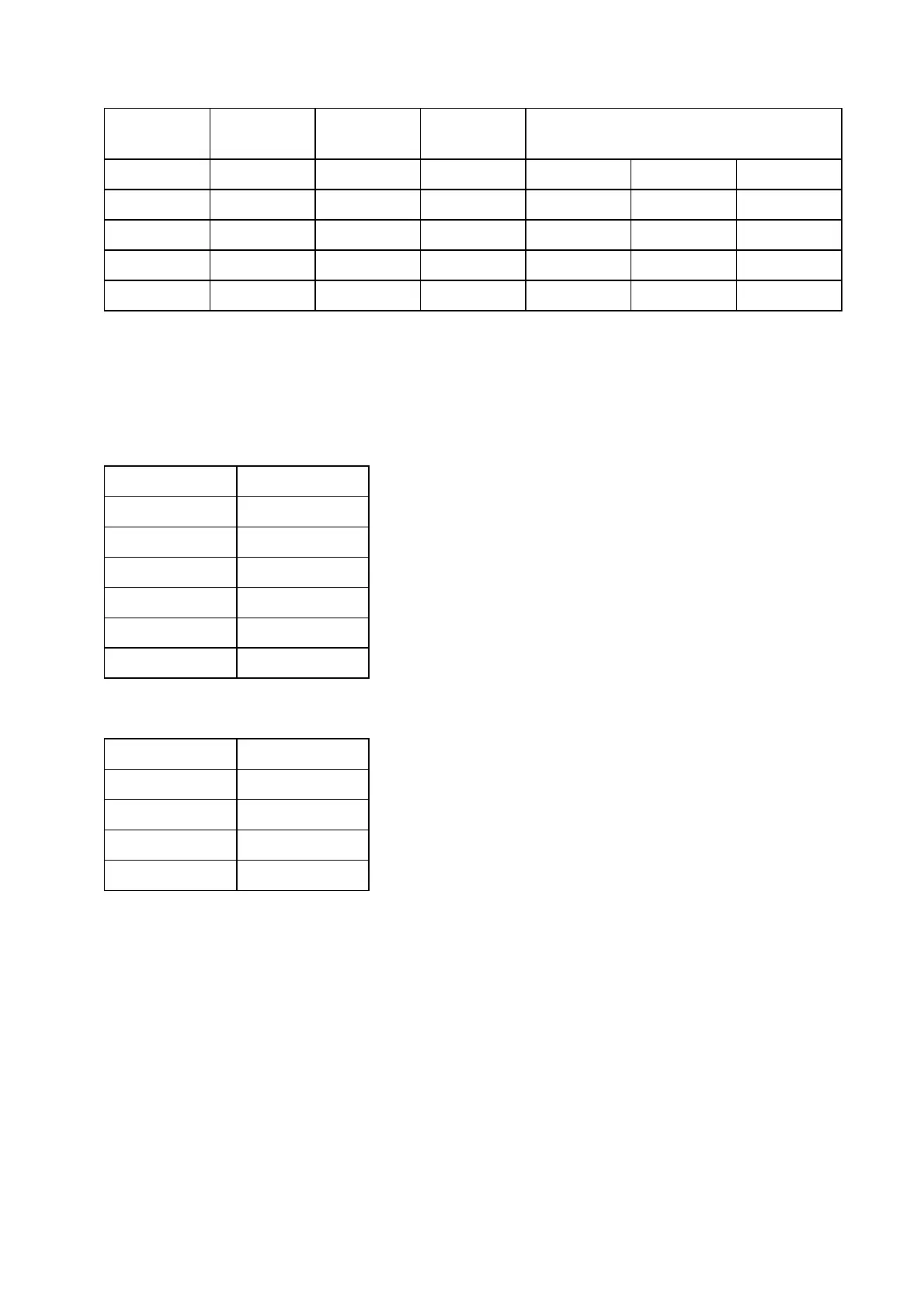
Current input Terminals Reference
voltage
Terminals Display
S2/S1 L/N Phase I
P
I
Q
I1 B3/B4 U23 A5/A7 1.00 ±3% ±0.0 ±3% In +1.0 ±3% In
I2 B5/B6 U31 A3/A7 1.00 ±3% ±0.0 ±3% In +1.0 ±3% In
I3 B7/B8 U12 A3/A5 1.00 ±3% ±0.0 ±3% In +1.0 ±3% In
E* B1/B2 U1 A3/A2 1.00 ±5% +1.0 ±5% In ±0.0 ±5% In
* Only SR-Types
Table 6.1
In order to check this, the following parameters should
be set:
Parameter Setting
I> 0,5 x In
tI> (V) EXIT
tI> (R) EXIT
IE> 0,5 x In
tIE> (V) EXIT
tIE> (R) EXIT
for relay assignment:
Parameter Relays
I> Alarm (V) _2__
I> Alarm (R) __3_
IE> Alarm (V) _2__
IE> Alarm (R) __3_
A test current of 1 x In is impressed upon the current
input. The voltage source is to be connected as pro-
vided for in Table 6.1. With an angle setting of 49
o
leading, relay 2 must respond and LED →← lights up
green. If the angle is now changed beyond the mar-
ginal regions, the LED →← changes from green to
red. Relay 2 drops and relay 3 responds. This test
must be repeated for current inputs 12 and 13.
In order to determine the direction in the earth current
circuit (SR version) refer to Fig. 8 with the characteristic
angle in the rigid grid (SOLI) and to Fig. 9 with the
characteristic angle in the grid with resistance earthing
(RESI).
To check the trip delays for forward and backward di-
rection they have to be set differently, because there's
only one trip relay for both directions.
Great care must be taken to connect the test current
and test voltage to the relay in correct polarity. In Fig-
ure 6.2 the relay and test source polarity are indi-
cated by a * mark near the terminals. The markings
indicate that the relay will trip in its maximum sensitive
angle when the voltage drop from the marked end to
the non-marked end in the voltage input circuit has
49° phase angle lagging the current flowing from the
marked end to the non-marked in the current input cir-
cuit. Of course, regardless of polarity, the current level
must be above the pickup value.


 To Next Page
 Loading...