30 TD_MRI1_06.05_GB
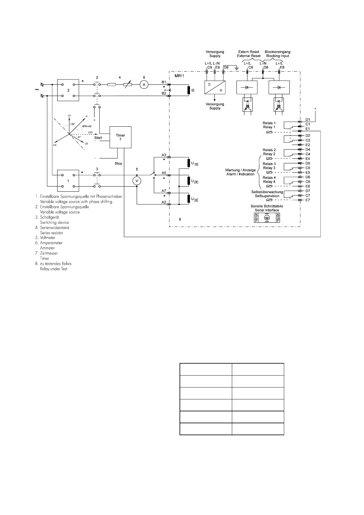
6.4.8 Test circuit earth fault directional feature
Figure 6.3: Test circuit
For testing relays with earth fault directional feature,
current and voltage input signals with adjustable
phase shifting are required. Figure 6.3 shows an ex-
ample of a single phase test circuit with adjustable
voltage and current energizing the MRI1 relay under
test.
For testing a relay with earth fault directional feature,
one of the input energizing quantity (voltage) shall be
applied to the relay with a constant value within its ef-
fective range. The other input energizing quantity (cur-
rent) and phase angle shall be appropriately varied.
With the aid of phase angle indicated on the display
the correct function of the relay can be checked (ER-
relay type).
Parameters I
E>
and I
E>>
should be set to EXIT.
The following measured values are shown:
Measured value LED
Earth current E, I
E>
Active share E, I
P
reactive share E, I
Q
Earth voltage E, U
E>
Angel E, I
E>
, U
E>


 To Next Page