Manual MRR1 SEG Electronics GmbH
DOK-TD-MRR1, Rev. B 5
3. Design
3.1 Connections
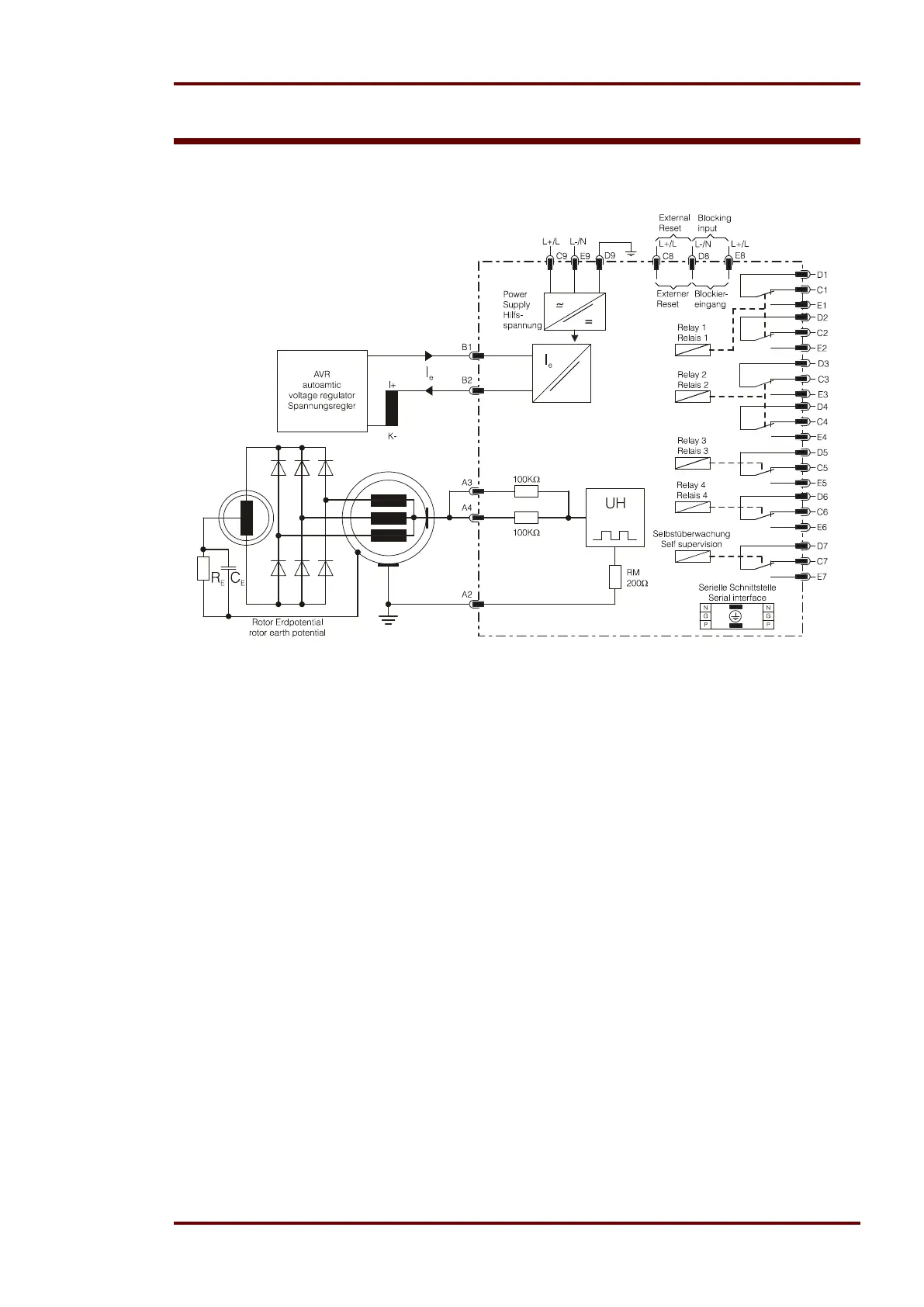
Figure 3.1: Connection diagram
3.1.1 Output relays
The MRR1 has 5 output relays. Relays 1 and 2 are provided with two change-over contacts each,
the other relays with one change-over contact each.
Function of relays 1 - 4 is programmable. Status of self-supervision is indicated by relay 5. The
relays are allocated to the following contacts :
Output relay 1: C1, D1, E1 and C2, D2, E2
Output relay 2: C3, D3, E3 and C4, D4, E4
Output relay 3: C5, D5, E5
Output relay 4: C6, D6, E6
Output relay 5: Self-supervision (internal fault of the relay) C7, D7, E7
All relays are normally off, only the self-supervision relay is normally on.
3.1.2 Blocking input
When required to inhibit the selected functions to be blocked, the auxiliary voltage has to be
switched to D8/E8 (please also refer to chapter 5.3.1).
3.1.3 External reset input
See chapter 5.2.2