Do you have a question about the Sega Game Gear VA1 and is the answer not in the manual?
Compares electrical components between Game Gear VA0 and VA1 models.
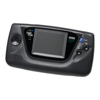
Identifies front and top components of the Game Gear console.
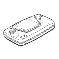
Details the components visible on the bottom of the Game Gear console.
Lists and illustrates common accessories for the Game Gear.
Step-by-step guide for disassembling the Game Gear unit.
Schematic details for the first section of the main circuit board.
Top and bottom views of the AC120V main circuit board.
Top and bottom views of the AC120V DC-DC converter board.
Top and bottom views of the AC120V sound circuit board.
Pinout and description for the main circuit board custom chip (GG QFP 144P).
Exploded view diagram of the main Game Gear assembly.
| Manufacturer | Sega |
|---|---|
| Type | Handheld game console |
| Generation | Fourth generation |
| Lifespan | 1990-1997 |
| Discontinued | 1997 |
| CPU | Zilog Z80 @ 3.58 MHz |
| RAM | 8 KB |
| VRAM | 16 KB |
| Sound | Mono |
| Battery life | 3-5 hours |
| Release date | October 6, 1990 |
| Media | Game cartridge |
| Display | 3.2 inch LCD |
| Power | 6 AA batteries or AC adapter |
| Dimensions | 210 mm x 113 mm x 38 mm |
| Weight | 400 g |
| Units sold | 10.62 million |