18
TECHNICAL GUIDE
Cal. 4F32A, 8F32A, 8F33A, 8F35A
32 Date dial guard
• How to remove
1. Lightly lift the A portion of the date dial guard
with tw eezers to clear it from the guide pin, and
then, m ove it in the clockwise direction until it
gets on the guide pin.
2. Release the B portion of the date dial guard in the
same m anner as you release the A portion, and
then, m ove it in the clockwise direction until it
gets on the guide pin.
3. Check that all the three protrusions of the date
dial guard have come off from the main plate, and
then, rem ove the date dial guard.
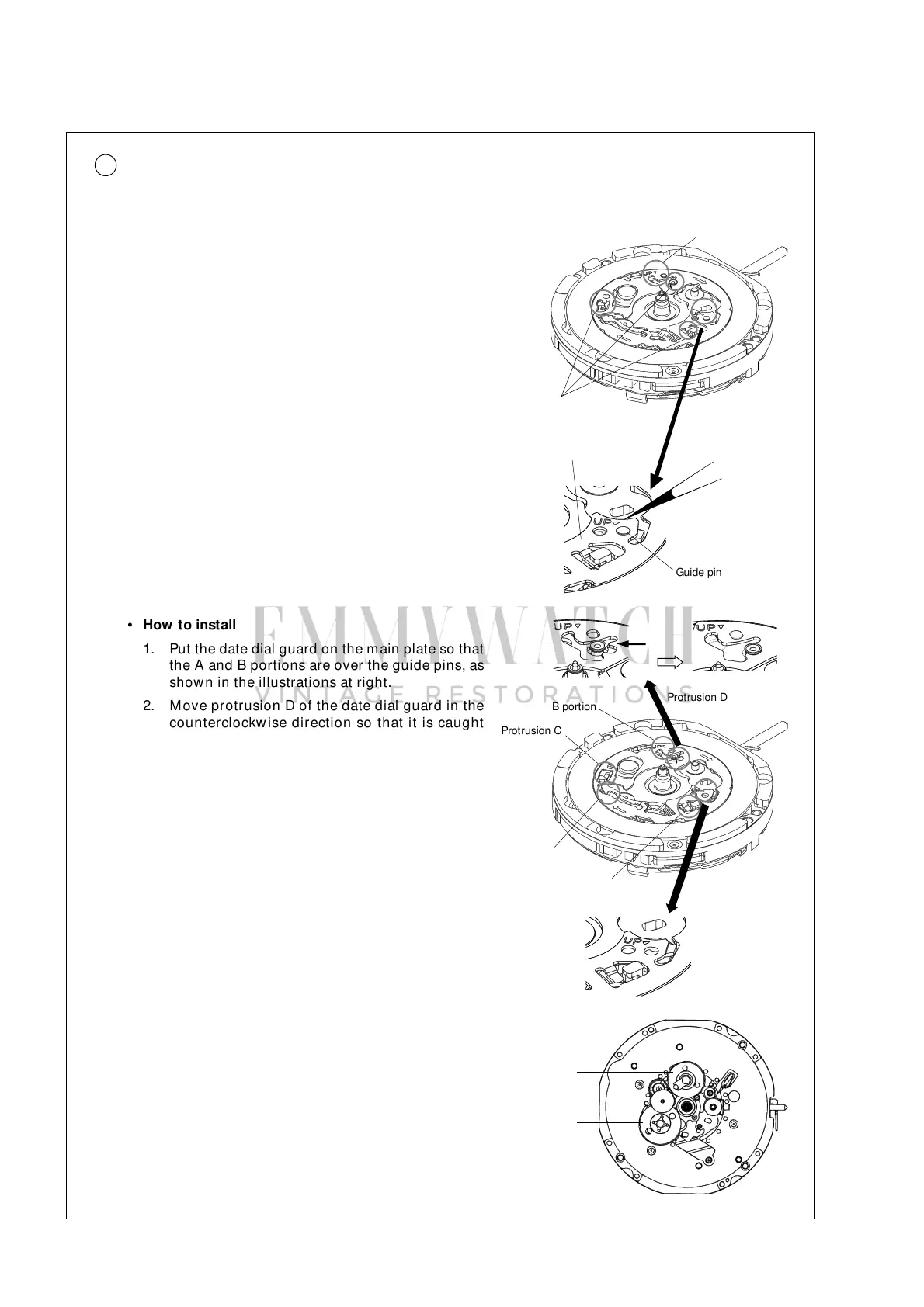
A portion
Protrusion D
Protrusion C
B portion
Protrusion E
Tw eezers
Guide pin
Protrusion
Date dial guard
A portion
Note: Take care not to deform the date dial guard, as
it is softly built.
• How to remove the date dial guard in replacing the date dial
(with the parts on the movement side installed)
Be sure to use the m ovem ent holder 4F8F-C for
exclusive use for replacing the date dial.
Unlike conventional movements, the date dial guard is not fixed with screws. It is set to the main plate
with the three protrusions, which are caught under the main plate by turning the guard. Then, it is fixed
by the two guide pins.
B portion
• How to install
1. Put the date dial guard on the main plate so that
the A and B portions are over the guide pins, as
shown in the illustrations at right.
2. M ove protrusion D of the date dial guard in the
counterclockw ise direction so that it is caught
under the m ain plate.
3. Sl ig h tly m o v e p r otr u si ons C an d E i n th e
counterclockwise direction alternately to set them
under the main plate. While doing so, set the A
and B portions of the date dial guard to the guide
pins.
Note: Take care not to press dow n the ultrasonic
rotor pinion while installing the date dial guard.
Ultrasonic
rotor pinion
Note: Never rem ove the date driving w heel and the
24-hour w heel. Otherw ise, the date driving
contact point spring and the 24-hour contact
point spring w ill com e off.
24-hour w heel
Date driving
wheel