SEL-451-6 Data Sheet Schweitzer Engineering Laboratories, Inc.
2
➤
Comprehensive Metering. The built-in, high-accuracy metering functions can improve feeder loading. Watt and
VAR measurements optimize feeder operation. Minimize equipment needs with full metering capabilities
including rms, maximum/minimum, demand/peak, energy, and instantaneous values.
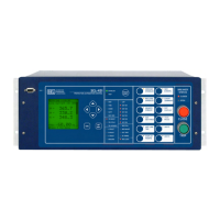
➤ Auxiliary Trip/Close Pushbuttons. These optional pushbuttons are electrically isolated from the rest of the relay.
They function independently from the relay and do not need relay power.
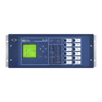
➤ Bay Control. The relay provides bay control functionality with status indication and control for disconnect
switches. The relay features control for as many as two breakers and status indication of as many as three breakers.
Numerous predefined user-selectable mimic displays are available; the selected mimic appears on the front-panel
screen in one-line diagram format. The one-line diagram includes user-configurable labels for disconnect
switches, breakers, bay name, and display for as many as six analog quantities. The relay features SEL
OGIC
programmable local control supervision of breaker and disconnect switch operations.
➤ Breaker Failure. High-speed (less than one cycle) open-pole detection logic reduces coordination times for critical
breaker failure applications. Apply the relay to supply breaker failure protection for all supported breakers. Logic
for breaker failure retrip and initiation of transfer tripping is included.
➤ IEC 60255-149 Compliant Thermal Model. The relay can provide a configurable thermal model for the protection
of a wide variety of devices. This function can activate a control action or issue an alarm or trip when equipment
overheats as a result of adverse operation conditions. A separate resistance temperature detector (RTD) module is
required for this application.
➤ Ethernet Access. The optional Ethernet card grants access to all relay functions. Use IEC 61850 Manufacturing
Message Specification (MMS) or DNP3 protocol directly to interconnect with automation systems. You can also
connect to DNP3 networks through a communications processor. Use File Transfer Protocol (FTP) for high-speed data
collection. Connect to substation or corporate LANs to transmit synchrophasors by using TCP or UDP internet protocols.
➤ Serial Data Communication. The relay can communicate serial data through SEL ASCII, SEL Fast Message,
SEL Fast Operate, M
IRRORED BITS
®
, and DNP3 protocols. Synchrophasor data are provided in either SEL Fast
Message or IEEE C37.118 format.
➤ Automation. The enhanced automation features include programmable elements for local control, remote control,
protection latching, and automation latching. Local metering on the large front-panel LCD eliminates the need for
separate panel meters. Serial and Ethernet links efficiently transmit key information, including metering data, protection
element and control I/O status, synchrophasor data, IEC 61850 Edition 2 GOOSE messages, Sequential Events
Recorder (SER) reports, breaker monitoring, relay summary event reports, and time synchronization. Apply expanded
SEL
OGIC
®
control equations with math and comparison functions in control applications. Incorporate as many as
1000 lines of automation logic to accelerate and improve control actions.
➤ Synchrophasors. You can make informed load dispatch decisions based on actual real-time phasor measurements
from relays across your power system. Record streaming synchrophasor data from the relay for system-wide disturbance
recording. Control the power system by using local and remote synchrophasor data.
➤ Breaker and Battery Monitoring. You can schedule breaker maintenance when accumulated breaker duty
(independently monitored for each pole) indicates possible excess contact wear. The relay records electrical and
mechanical operating times for both the last operation and the average of operations since function reset. Alarm
contacts provide notification of substation battery voltage problems (as many as two independent battery monitors
in some SEL-400 series relays) even if voltage is low only during trip or close operations.
➤ Digital Secondary Systems (DSS) Technologies. You can order the relay as either an SV subscriber relay or a
TiDL relay. DSS capable relays receive current and voltage information that is published by remote merging units
instead of standard PT and CT inputs. DSS technologies reduce copper cable lengths and associated installation
labor costs and improve the overall safety of the substation.
➤ IEC 61850-9-2LE SV Relay. The SV subscriber relay can subscribe to current and voltage information that is
published by as many as seven remote SV merging units that are compliant with the IEC 61850-9-2LE guideline.
➤ TiDL Relay. The TiDL relay can receive current and voltage information from as many as eight SEL-TMUs (TiDL
Merging Units) over direct point-to-point fiber-optic connections. The TiDL relay automatically synchronizes data
collection, alleviating the need or impact of an external clock on protection.
➤ Selective Protection Disabling. The subscriber or TiDL relay provides selective disabling of protection functions
by using hard-coded logic or available torque-control equations in case of a loss of communications between your
merging unit and relay that results in the loss of relevant analog data.
➤ Current Summation. The relay can combine multiple SV stream currents to simplify external wiring.