Schweitzer Engineering Laboratories, Inc. SEL-451-6 Data Sheet
7
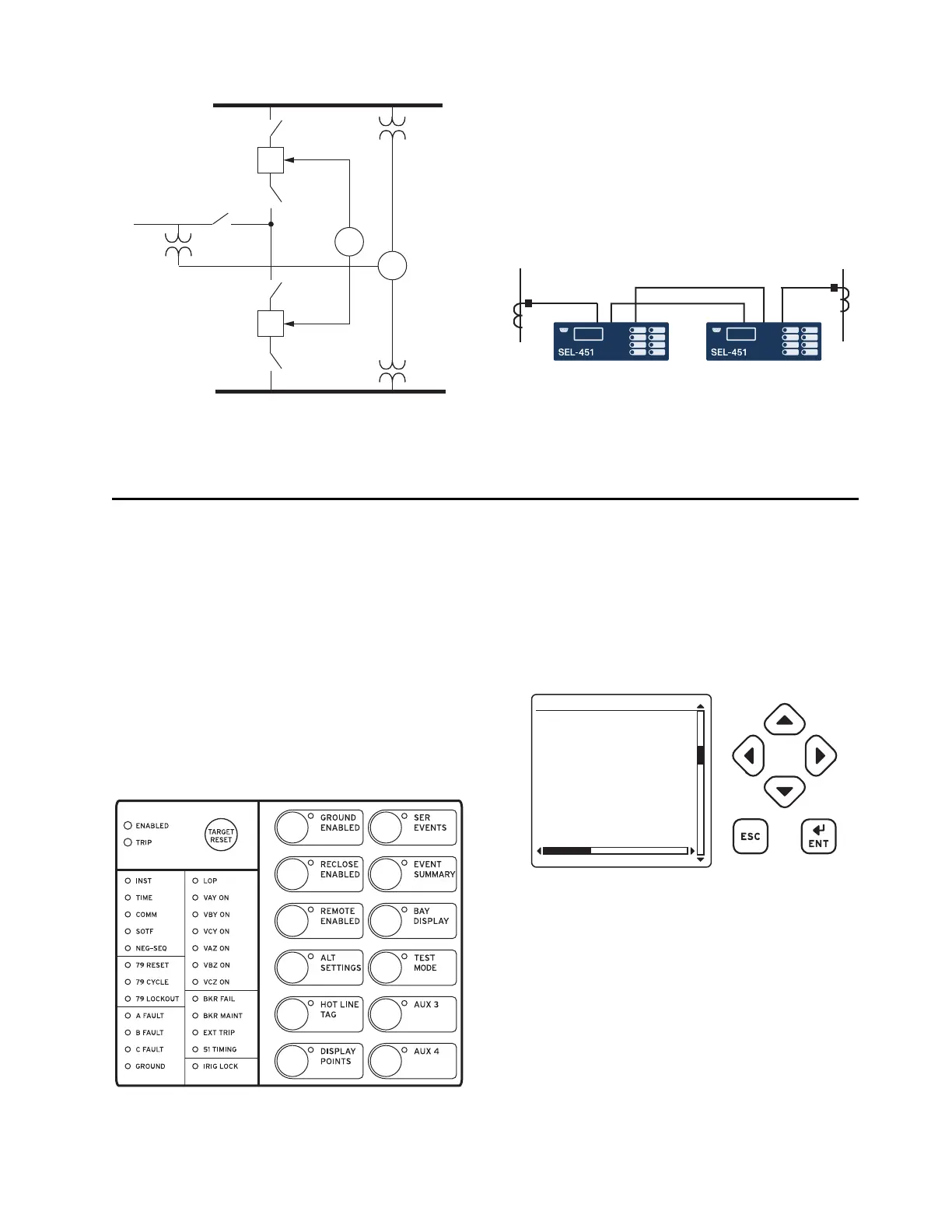
Backup Protection
Add reliability and dependability by providing indepen-
dent backup protection without increasing relay count.
Use each SEL-451 to provide primary directional over-
current protection with backup nondirectional overcur-
rent protection on the adjacent feeder. For additional
flexibility, use the available I/O or M
IRRORED BITS com-
munications to switch protection upon loss of one relay.
Additional Features
Front-Panel Display
The LCD shows event, metering, settings, and relay self-
test status information. The target LEDs display relay
target information as shown in Figure 7.
Figure 7–Figure 8 show close-up views of the front panel
of the SEL-451. The front panel includes a 128 x 128
pixel, 3" x 3" LCD screen; LED target indicators; and
pushbuttons with indicating LEDs for local control func-
tions. The asserted and deasserted colors for the LEDs
are programmable. Configure any of the direct-acting
pushbuttons to navigate directly to an HMI menu item,
such as events, bay display, alarm points, display points,
or the SER.
The LCD is controlled by the navigation pushbuttons
(Figure 8), automatic messages the relay generates, and
programmable analog and digital display points. The
rotating display scrolls through the bay screen, alarm
points, display points, and metering screens. Each dis-
play remains for an adjustable time (1–15 s) before the
display continues scrolling. Any message generated by
the relay because of an alarm condition takes precedence
over the rotating display.
Bay Control
The SEL-451 provides dynamic bay one-line diagrams
on the front-panel screen with disconnect and breaker
control capabilities for numerous predefined user-select-
able bay types. You can download the Grid Configurator
interface from selinc.com to obtain additional user-
selectable bay types. The bay control can control as
many as ten disconnects and two breakers, depending on
the one-line diagram selected. Certain one-line diagrams
provide status for as many as three breakers and ten dis-
connect switches. Operate disconnects and breakers with
Figure 5 Two-Breaker Reclosing With Synchronism Check
52-1
52-2
Line
Bus 2
Bus 1
79
25
Figure 6 Using Two Cross-Connected SEL-451-5 Relays
to Provide Primary and Backup Protection for Two Feeders
Figure 7 Factory-Default Status and Trip Target LEDs
(12 Pushbutton, 24 Target Option)
Figure 8 Front-Panel Display and Pushbuttons
03/15/01 GROUP 1
00:00:05.387
EVENT: BCG T
LOCATION: 48.47
FREQ: 60.00
SHOT: 3P=1
BK1 OPEN
BK2 CLOSED
EVENT SUMMARY 10002


 To Next Page