The contents of this chapter are of vital importance and the-
refore necessary for operation of the warranties. The manu-
facturer accepts no liability if the operator fails to observe
the above precautions and instructions.
4.0 MACHINE DESCRIPTION
Sistor 82 is a generator for plasma cutting, which is ideal for
medium and heavy structural work.
Sistor 82 uses compressed air as its only gas source, which can
be supplied from a normal compressor or from a suitably sized
centralized plant. It is able to carry out, cheaply, cuts of a high
quality up to a thickness of 25/30 mm in carbon steel, stainless
steel and aluminium. Nitrogen can also be used as gas with
reduced thickness and greater cutting precision.
The current is stable, precise and unaffected by variations in the
supply voltage, the height of the cutting arc, the progression
speed and the thickness of the metal to be cut.
This high performance is made possible thanks to the use of
state-of-the-art technology, which employs the high commuta-
tion speed possible with the latest electronic components.
There are safety systems that cut off the power circuit when the
operator comes into contact with live parts of the machine, as
well as controls to reduce the wear on the electrode and nozz-
le at the moment of striking the cutting arc. The ignition of the
cutting arc takes place with the use of a high frequence voltage
discharge, that becomes automatically cut off when the opera-
tion is complete, thus limiting the emission of radio interferen-
ce in the rest of the cutting process.
The generator is equipped with:
- one torch fitting,
- an earth socket,
- front panel,
- rear panel.
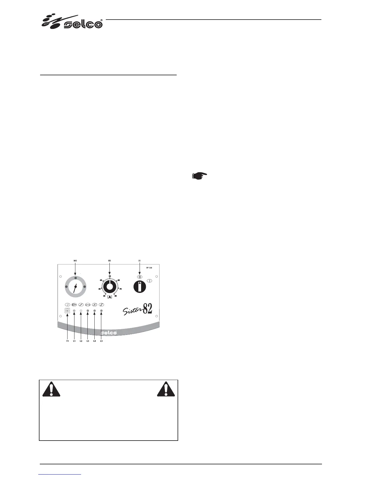
4.1 Front control panel (Fig.1)
Fig. 1
*
I1: Off/On switch
Turns on the electric power to the welder.
It has two positions, "O" off, and "I" on.
* With the I1 switch in the "I" on position, the welder is
operational.
* The welder is connected to the mains supply even if the I1
switch is in the "O" position, and therefore there are elec-
trically live parts inside it. Carefully follow the instruc-
tions given in this manual.
* L1 : Voltage warning light green led.
Comes on with the start switch (Fig.1) "I1" in position "I" and
indicates that the plant is on and there is voltage.
* L2 : Safety device warning light yellow led.
lndicates that the safety devices like thermal cutout.
With "L2" on, the power source remains connected to the
supply mains, but does not supply output power.
"L2" remains on until the fault has been removed and in any
case until the inner temperatures are not within the normal
values; in this case it is necessary to leave the power source
on to exploit the operating ventilator and reduce the time
when it is not active.
* L3: compressed air alarm green led.
Means that the pressure of compressed air is below 3 bar, too
low for proper functioning. The generator has no power output.
* L4: Power output light red led.
Comes on when the arc is sparked, both during cutting and
when not cutting, and goes out as soon as the arc finishes.
* L5: torch cap alarm green led.
Means that the torch cap has not been properly tightened.
The generator has no power output.
In the event of an alarm, the operating condi-
tions are restored only if the cause is removed.
* R1: Potentiometer for setting the cutting current.
Allows you to continuously adjust the cutting current. This
current stays unchanged during cutting when the supply and
cutting conditions vary within the allowed ranges.
* T1: gas test pushbutton.
Allows impurities to be removed from the compressed air cir-
cuit and preliminary capacity and pressure settings to be
made with no power output.
* M1 :displays the air pressure value for the cutting process.
14
WARNING