CPU 72x
24.05.2019 page 5
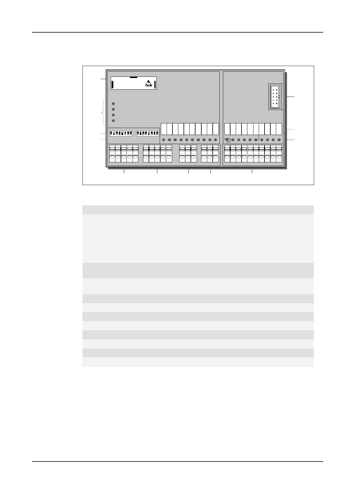
1.2.3 Processor Module CPU 723-T
Fig.03: Processor module CPU 723-T
Legend:
LEDs:
UC/BAT: Power supply and lithium accumulator/battery status
RUN: CPU operation mode
CAN1: CAN communication on CAN bus 1
CAN2: CAN communication on CAN bus 2
S: Short circuit on the digital output
DIP switch S1 for CAN bus:
Adjustment of the CAN bit rate and the node address
DIP switch S2 for CPU configuration:
Adjustment of the start-up behavior and the RS-232C
Connector for CAN bus 1 and power supply (UC)
Terminal strips for digital inputs
Terminal strips for digital inputs and outputs
Link connector for subsequent extension modules
12
11
10
987
4
3
2
1
65
FMC 701
S
CPU 723-T
Input Output Input
UC/BAT
RUN
CAN2
CAN1
S1 S2
0V 00 01 0V 00US 01 02 03 04 05 06 07