Selkirk Canada CorporationSelkirk Canada Corporation
Selkirk Canada CorporationSelkirk Canada Corporation
Selkirk Canada Corporation
1400 CALIFORNIA AVENUE
BROCKVILLE, ON K6V 5V3
TEL: 1-800-267-8178
FAX: 1-800-663-3620
www.selkirkcanada.com
info@selkirkcanada.com
8. Connect and fasten the appropriate 8” ducting to the
Damper Sleeve with a minimum of 3 sheet metal screws (not
supplied) ensuring that a 25mm (1") minimum clearance is
maintained between the ducting and any combustible
materials. Support the ducting in accordance with local
codes (see photo below).
Support
Bracket
Prewired
Junction Box
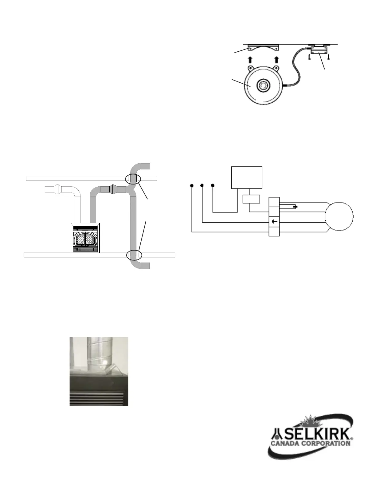
9. Position the blower in the horizontal ducting system for
easy mounting with supplied mounting bracket (see Figure 8)
ensuring that a 25mm (1”) minimum clearance is maintained
to any combustible materials. Some consideration should go
into the planning to ensure that the blower noise does not
affect rooms you would like kept quiet.
Blower
10. All wiring must be carried out in accordance with National
Electrical Code, and all applicable state and local buildings
codes. Figure 9 provides a wiring diagram.
Speed
Control
Regulator
Blower
Brown
Black
Yellow / Green
Blue
Fig. 7 - Shown with 8” Spiral Ducting
WARNING! Only one Central Heating Kit to be installed in the
system serving Selkirk’s model HE-EPA. One primary 8”
ducting and blower per installation.
Figure 6 - Shaded Alternate Ducting Configurations
Upper
Level
Lower
Level
HE-EPA
Wood
Burning
Fireplace
Maintain a
25mm (1”)
air space
clearance to all
combustible
materials
120 VAC 60 Hz
L2 G L1
SLS*
SLS* - Safety Limit Switch
L1 - Supply
G - Ground
L2 - Common
Figure 9 - Wiring Diagram
Figure 8 - Mounting of Blower
5. Make provision to route a 120V electrical supply to the
location where the blower will be mounted. Supply wiring to
the motor will be rated for 125° C or higher. The blower, when
installed, must be electrically grounded in accordance with
local codes or, in the absence of local codes, with the lates
edition of the National Electrical Code, ANSI/NFPA 70 (USA)
or CSA-C22.1 (Canada).
6. The ducting for the Central Heating system can be
accomplished with a 203mm (8”) diameter spiral, flex or rigid
duct.
7. When installing the ducting a 25mm (1”) minimum air space
clearance to all combustible materials must be maintained.
Ensure that the installation of the ducting will conform with all
federal and municipal codes requirement. See Figure 6 for
alternate ducting configuration.
 Loading...