19
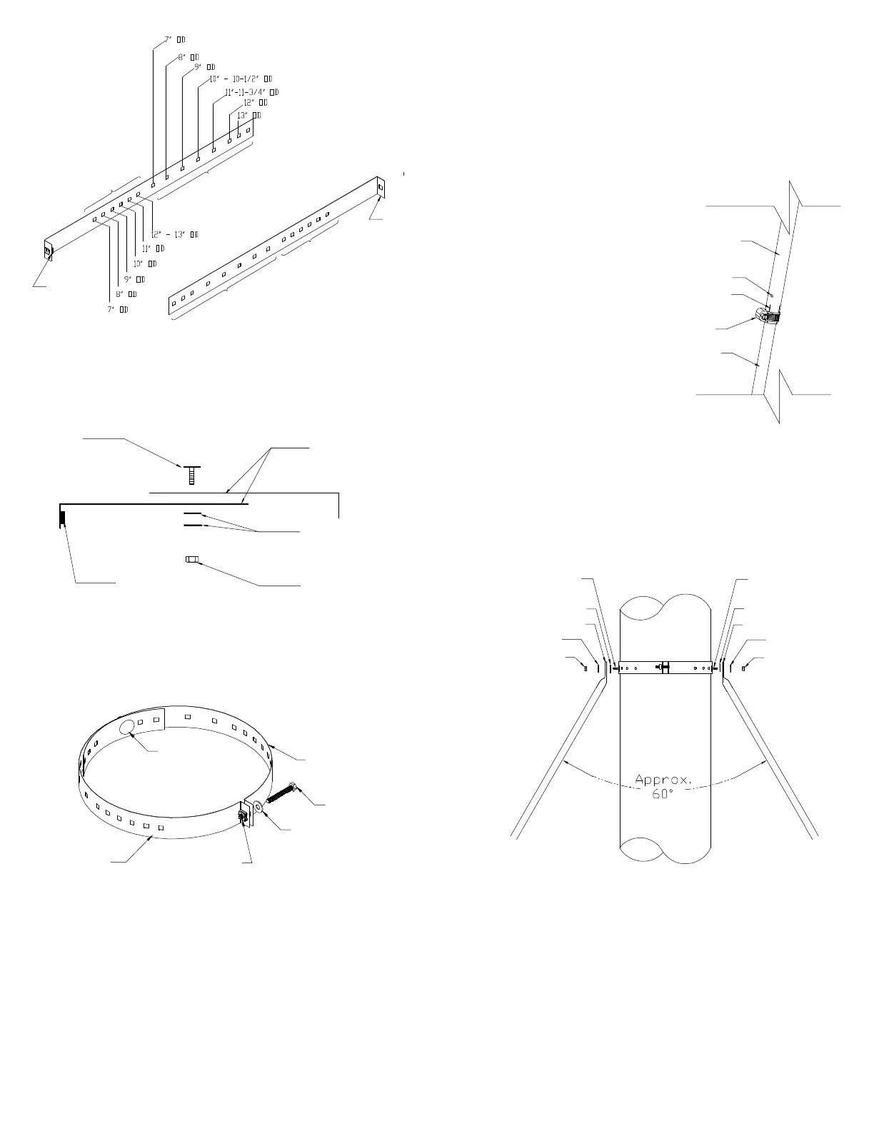
Holes for Telescoping
Legs to Support Band
Holes for Support Band
Cage Nut
Holes for Support Band
Holes for Telescoping
Legs to Support Band
Assembly of Universal
Support Band (2 Halves)
Figure 29
Figure 30
Topview assembly of Support Band -
Elevator Bolt, Washers and Nut
Flanged Nut
Flat Washers
Support Band
Halves
Elevator
Bolt
Cage Nuts
Assembly of Support Band:
C. Form the band into a circle (see Figure 31) and loosely connect tabs using
the supplied 2” bolt into the cage nut located on one of the two formed
tabs.
Boulon
1/4 x 2 po
Figure 31
Universal Support Band
formed into a circle
Cage Nut
One of 2 halves
of Support Band
One of 2 halves
of Support Band
Elevator
Bolt
Flat Washer
D. Select the hole in each half that corresponds to the OD of the chimney.
Insert an elevator bolt in each of the holes (1 per side).
E. Position the Support Band approximately two thirds of the way up the
chimney height (see Figure 35). The preferred location is next to a joint,
immediately above or below a Locking Band. Secure Support Band by
tightening the 2” bolt. NOTE: Only one chimney joint should be above
a Roof Guy Kit. An additional Roof Brace Kit may be required for taller
systems.
F. Assemble the telescoping legs by sliding the supplied hose clamp over
larger diameter leg and then inserting smaller diameter leg into larger
diameter leg. Temporarily hold legs together by tightening the hose
clamp over the cut section of larger diameter leg (see Figure 32). Repeat
for the other telescoping leg assembly.
G. Place a flat washer on the elevator bolts and attach the angled end of each
of the telescoping legs to the 2 elevator bolts on the Support Band with
washer and nut (see Figure 33).
Assembly of Telescoping
Legs with Hose Clamp
Figure 32
Larger Diameter
Telescoping Leg
Cut Section of Larger
Telescoping Leg
Smaller Diameter
Telescoping Leg
Pilot Hole for
Securing Screw
Hose Clamp
H. Attach the other end of each telescoping leg assembly to an Angle Bracket
using one (1) 1/4-20 X 1” bolt and nut (see Figure 34).
Elevator Bolt
Flat Washer
Flanged Nut
Elevator
Bolt
Flat Washer
Flanged Nut
Figure 33
Assembly of Telescoping
Legs to Support Band
Flat Washer Flat Washer
I. Determine the location of the two Angle Brackets on the roof structure.
Ensure the fasteners are into rafters or framing and not just roof
sheathing. Secure the Angle Brackets to the roof structure using two
(2) 1/4 X 2” lag screws per brackets (see Figure 34). Apply a thin layer
of caulking under the angle bracket (before securing in place) as well as
over the lag screw heads.
Angled end of Leg
Angled end of Leg