rev.3.1 dated 30/06/14
VTS300 3-PHASE SLAVE REGULATOR
SELPRO – Via P.G. Piamarta 5/11 – 25021 Bagnolo Mella (BS) – www.selpro.it – info@selpro.it - Tel. +39 030 6821611 – Fax +39 030 622274
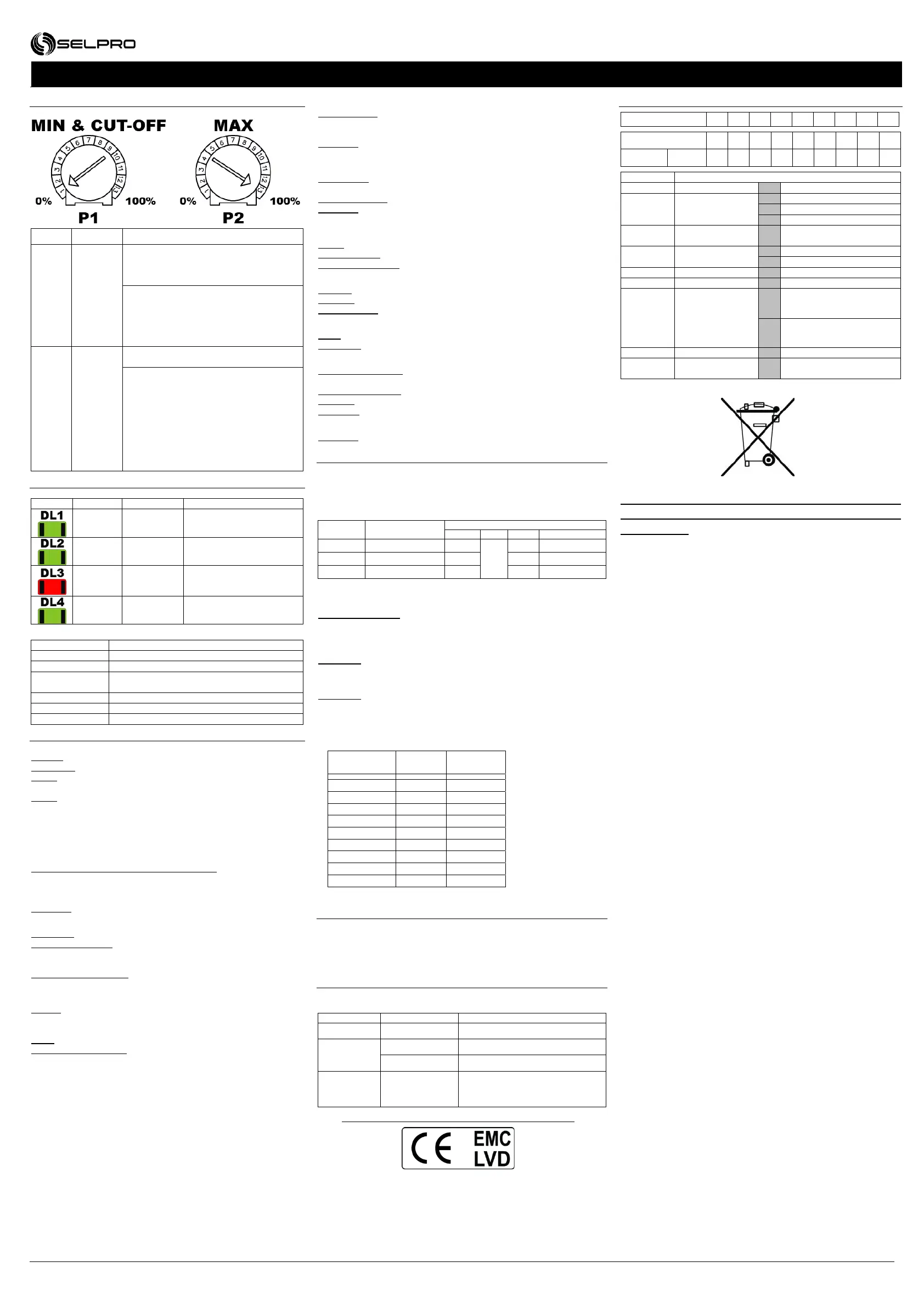
5. Trimmer Regulation limits
5.1. Regulation limits
Trimmer Label Description
P1
MIN/
CUT-OFF
Use as minimum voltage (MIN)
DSw4 = OFF (range from 0-100%).
Turn P1 clockwise to the required
minimum voltage.
Use as CUT-OFF
(shutdown point)
DSw4 = ON (range from 0-100%).
Once the minimum voltage is set, turn
DSw4 ON and press SB1 (reset). Cut-Off
will be set to minimum voltage.
P2
MAX
Maximum speed limit settings (range 0-
100%).
Settings procedure if maximum regulator
speed input signal is not available:
Remove signal connections from M3.
Set the regulator in
0-10 Vdc mode (see point 3.3.2)
Short circuit IN with VR (M3 terminals 1
and 4). The regulator runs at maximum
speed.
Turn P2 counter-clockwise to set the
required maximum voltage.
6. SIGNALS
6.1. Led
LED COLOR LABEL DESCRIPTION
GREEN PWR
Power on
(light on)
GREEN CPU RUN
Microprocessor running
(blinking light)
RED FAIL
Fault alarm
(blinking light)
(see point 6.2)
GREEN -
RL1 relay excited
(light on)
6.2. Alarm blink code (DL3) in order of priority
NR. BLINKS DESCRIPTION
1 Board temperature over limit (> 85 °C)
2 Phase loss
3
T.K. contact open (DSw5 = ON and DSw6 =
OFF)
4 Input signal over range
5 Input signal under range
6 Incorrect dip switch settings
7. TECHNICAL SPECIFICATIONS
Power supply:
Voltage: 400 Vac (±10%) three-phase (230 Vac upon request).
Frequency: 50/60 Hz automatic frequency recognition
Surge: for installation category II (4 kV)
(> 500 Vac surge filters ON).
Mains: monitoring on all 3 phases.
Ground connection:
VTS300 controllers are compatible with the different Ground
connections: IT – TT - TN.
Current:
Rated RMS current @ 50 °C room temperature:
VTS308: 8 A < 50 °C; > 50 °C -0.6 A/°C
VTS312: 12 A < 50 °C; > 50 °C -0.6 A/°C
VTS320: 20 A < 50 °C; > 50 °C -0.6 A/°C
Overload: 150% of rated current (=10” every 3’)
Power:
Command: 5 V A
Dissipated in. 4 W/A: VTS308 32 W @ 8 A
VTS312 48 W @ 12 A
VTS320 72 W @ 20 A
Functional characteristic: SLAVE regulator
Direct function; output increases as input increases
Input signals and contacts:
Analog: 0-10 Vdc, 0-5 Vdc (Ri = 10 kΩ)
0-20 mA, 4-20 mA (Ri = 100 Ω)
Logic: PWM signal from 3 to 20 Vdc with positive polarity
“ON/OFF” clean contact: S0 programmable contact
(see point 3.3.3).
Output signals and contacts:
Auxiliary power:
20 Vdc (±20%), ≤ 20 mA not stabilized and protected against short circuit
5.0 Vdc/10,0 Vdc (±1.0%), ≤ 20 mA protected against short circuit
RL1 relay: COM, NC, NO contacts for alarm
3 A @ 250 Vac – 3 A @ 30 Vdc
Alarms:
In command: 0-5 Vdc: Vin ≤ 5.5 Vdc; 0-10 Vdc: Vin ≤ 11 Vdc
0-20 mA: Iin ≤ 24 mA; 4-20 mA: 2 mA ≤ Iin ≤ 24 mA
Mains monitoring: phase loss
Regulator: working temperature control with internal probe
(< 85 °C).
Protections:
Surge: As per EN 61000-4-5: surge category II (4 kV)
Auxiliary power: with PTC sensor for short circuit protection
Internal temperature: internal thermal protection
Case:
Material: GW-PLAST 75 (temperature < 85 °C) and aluminum
Pollution: for high pollution using the wire clamp kit
Fire resistance: category D
Insulation:
Case: class I (use of grounded PE protection)
Command: 4000 Vac between command input and mains voltage parts
Working conditions:
Working temperature: from -20 °C to 50 °C ; use
Start/Stop contact if T ≤ -10 °C
Storage temperature: from -20 °C to 70 °C
Humidity: from 0% to 85% non-condensing relative humidity
Vibrations: ≤ 1 g (9.8 m/s²)
Assembly:
Assembly: wall mount in vertical position only.
8. CIRCUIT BREAKER AND SHORT CIRCUIT PROTECTION
A short circuit and/or overload device must be installed upstream from the
VTS308, VTS312 or VTS320 regulator; this protection must be supplied
by the installer and can be made up of:
Three-phase circuit breaker with ‘AC’ cut-off curve
Triple ultra-fast fuses, to protect semi-conductors
Model Circuit breaker
Protection fuses - SRC
Type Vac Amp P/N
VTS308
16 A
10x38
690
16 FR10GB69V16
VTS312
24 A
10x38 16 FR10GB69V16
VTS320
40 A
14x51 25 FR10GB69V25
The use of these protections safeguard regulation device electrical
integrity.
SURGE ARRESTER :
Electrical protection inserted between the regulator power supply and
grounding, that protects the device from transitory power surges up to 480
Vac.
WARNING:
Disconnect the faston contact from the PE ground reference, in the
electrical rigidity test.
WARNING:
For DIFFERENTIAL protection systems, use components with grounded
current dispersion ≥ 60 mA.
The VTS300’s dispersion current to Ground, it’s about 4 mA
The following table shows the measured values:
Supplied
phases
Current
(mA)
Regulation
output
L1 – L2 – L3 < 4 0%
L1 – L2 – L3 < 4 100%
L1 – L2 – L3 < 13 15%
L1 – L2 < 8 0%
L2 – L3 < 8 0%
L1 – L3 < 8 0%
L1 < 12 0%
L2 < 12 0%
L3 < 12 0%
9. MANUFACTURER'S DECLARATION
This instrument was designed and constructed for use in Industrial
environments and meets the following community directives:
Machinery Directive 2006/42/CE as amended
Low Voltage Directive 2006/95/CE and 93/68/CE
EMC 2004/108/CE directive as amended
10. COMMUNITY DIRECTIVES AND TECHNICAL STANDARDS
The essential directive requirements are met by compliance with
“generic standards” for the industrial environment.
Directive Code Standard Description
2006/42/CE EN 60204-1 Machine safety and electrical system
2006/95/CE
EN 60204-1 Machine safety and electrical system
EN50178 Power installation electronic equipment
2004/108/CE EN61800-3
Variable speed electric drives.
Part 3 : Product standard for
Electromagnetic compatibility and
specific test methods
With reference to EMC compatibility, according to markings:
11. CODE
ZN VTS a bb cc d e f g h i
POSITION a bb cc d e f g h i
EXAMPLE ZNVTS 3 12 40 1 0 0 S 0 0
Position Description
a power type 3 three-phase
bb
Rated current
08 8 A
12 12 A
20 20 A
cc
power supply
voltage
40 400 Vac (±10%) - 50/60 Hz
d motor outputs
1 1 motor outputs
4 4 motor outputs
e not used 0 -
f not used 0 -
g
case protection
grade
S IP55
G IP20
h customizations 0 Selpro standard version
i revision index 0
Global product update
index
The instrument must be disposed of according
to local electric and electronic device disposal
regulations.

 Loading...