rev.3.1 dated 30/06/14
VTS300 3-PHASE SLAVE REGULATOR
SELPRO – Via P.G. Piamarta 5/11 – 25021 Bagnolo Mella (BS) – www.selpro.it – info@selpro.it - Tel. +39 030 6821611 – Fax +39 030 622274
1. PREPARATIONS
1.1. Important
Read these instructions carefully before installation.
Before use, follow all the installation and electrical connection
instructions.
Keep these instructions with the regulator for future use.
Observe current technical and safety regulations.
The device must be professionally installed and commissioned by a
qualified technician. INCORRECT installation may cause damages.
Before turning on device power, always check that it is correctly
grounded.
DO NOT tamper with or REMOVE internal regulator components;
this NULL AND VOIDS THE WARRANTY and can cause damages.
The user must be protected against electrical shock and the motor
must be equipped with overload protection, as per current pertinent
regulations.
According to safety regulations, protection against any contact with
live parts must be ensured by correct device installation; all parts
that ensure protection must be secured so as irremovable without
the help of a tool.
DO NOT turn on the regulator without the protection lid.
NEVER touch electrical circuit parts when the power is on.
Install the regulator away from direct sunlight so as not to overheat
the case.
Make sure working conditions (working temperature, humidity, etc.)
are within the indicated limits (see point 7).
Do not install the device near heat sources (resistances, hot air
ducts, etc.) where room temperature can exceed 50 °C, devices
that generate strong magnetic fields, sites subject to rain, humidity,
dust, excessive mechanical vibrations or shocks.
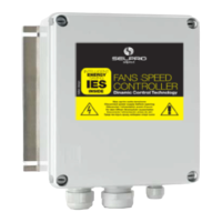
2. VTS300 REGULATOR UNIT DESCRIPTION
2.1. Overview
The VTS series three-phase regulators are built on a Vetronite(R)
support in an IP55 grade GW PLAST box. The control zone is at the
top of the board while the power zone is at the bottom.
In addition to the M3 and M4 terminal boards, regulation, connection
and signal devices are found in the control zone.
The fan speed command varies according to the command signal
received from the input. Output increases as input increases.
2.2. Key
VTS300 key
1 - Wire clamps - connection wires
2 M1 Three-phase output terminal board (U-V-W) + load
GND
3 M2 Three-phase power supply terminal board (L1-L2-
L3) + PE
4 - TPN lock screws with max 2.5 N m torque
5 - Wall mount perforated fin
6 - GW PLAST case
7 P1 Minimum voltage settings (MIN / CUT-OFF)
8 P2 Maximum voltage settings (MAX)
9 M3 Command input terminal board
10 M4 Alarm relay terminal board
11 DL.. Signal led
12 DSw Programming dip switch (0-10Vdc std setting)
13 SB1 Reset button
2.3. Mechanical dimensions
Model
Plate data Mechanical dimensions Weight(*)
A kV A IP A B C E F Kg
VTS308 8 5.5 55 225 235 114 213 200 2.3
VTS312 12 8 55 225 230 128 213 200 2.5
VTS320 20 14 55 225 230 158 213 200 3.8
* Packaging included
3. INSTALLATION
3.1. INSTALLATION
Vertically install the device with the wire inlet facing down. To permit
correct heat dissipation, guarantee ≥150 mm clearance over and under
the regulator.
Reassemble and make sure the external protection lid is fully closed.
3.2. Electrical connections
Flexible wire section.
Signal: rated section 1.5 mm² (15 AWG)
Power: VTS 308 ≥ 1.5 mm² (15 AWG)
VTS 312 ≥ 2.5 mm² (13 AWG)
VTS 320 ≥ 4.0 mm² (11 AWG)
N.B. Protection devices: see point 8.
3.2.1. Power (M1) and load (M2*) connection:
(*)The regulator can be set to directly connect no. 4 fans (Three-phase +
Ground) upon request
3.2.2. Command signal connections (M3)
M3 Terminal Label Description
6 GND Reference grounding
5 S0 ON-OFF input (see point 3.3.3)
4 VR
Reference voltage output
+5.0 Vdc/+10.0 Vdc (±1.0%)
(automatic switching)
3 V+
Power supply voltage output
+20 Vdc (±20%)
2 GND Reference grounding
1 IN Command signal input
3.2.3. Alarm relay connection (M4)
Termi
nal
Label Description
3 NO
Normally open contact
2 NC
Normally closed
contact
1 COM
Shared terminal
3.3. Dip-Switch function settings (DSw1 – DSw6)
DSw Description
1,2,3 Command signal selection (see point 3.3.2)
4
OFF = P1 (MIN) minimum voltage settings
ON = P1 cut-off voltage settings
5,6 ON-OFF input function (see point 3.3.3)
3.3.1. Default settings
3.3.2. Command input function programming
WARNING Press button SB1 after changing DSw settings to apply
changes..
DSw1 DSw2 DSw3
Description
OFF OFF OFF 0-20 mA signal
ON OFF OFF 4-20 mA signal
OFF ON OFF 0-10 Vdc signal
ON ON OFF 0-5 Vdc signal
OFF OFF ON PWM signal
ON ON ON Cos Phi calibration (reserved)
3.3.3. Functional programming for the ON-OFF input (S0)
DSw5 DSw6
Description
OFF OFF Start/Stop function (open = start)
ON OFF Thermal contact function (closed = start)
ON ON Output function at 100% (closed = 100%)
OFF ON Output function at MAX (closed = MAX (P2))
4. FUNCTIONAL CHARACTERISTIC