4
X
SEMPELL SERIES VSE/VSR FULL LIFT AND NORMAL SAFETY RELIEF VALVE
OPERATING INSTRUCTIONS
3.3 Installation instructions
NOTE
Clean pipes before installing safety valves as
otherwise the valve seats can be damaged by
foreign bodies when discharging!
Remove transport protection just before
installation.
Check plant identification and details on the
nameplate.
3.3.1 Installation
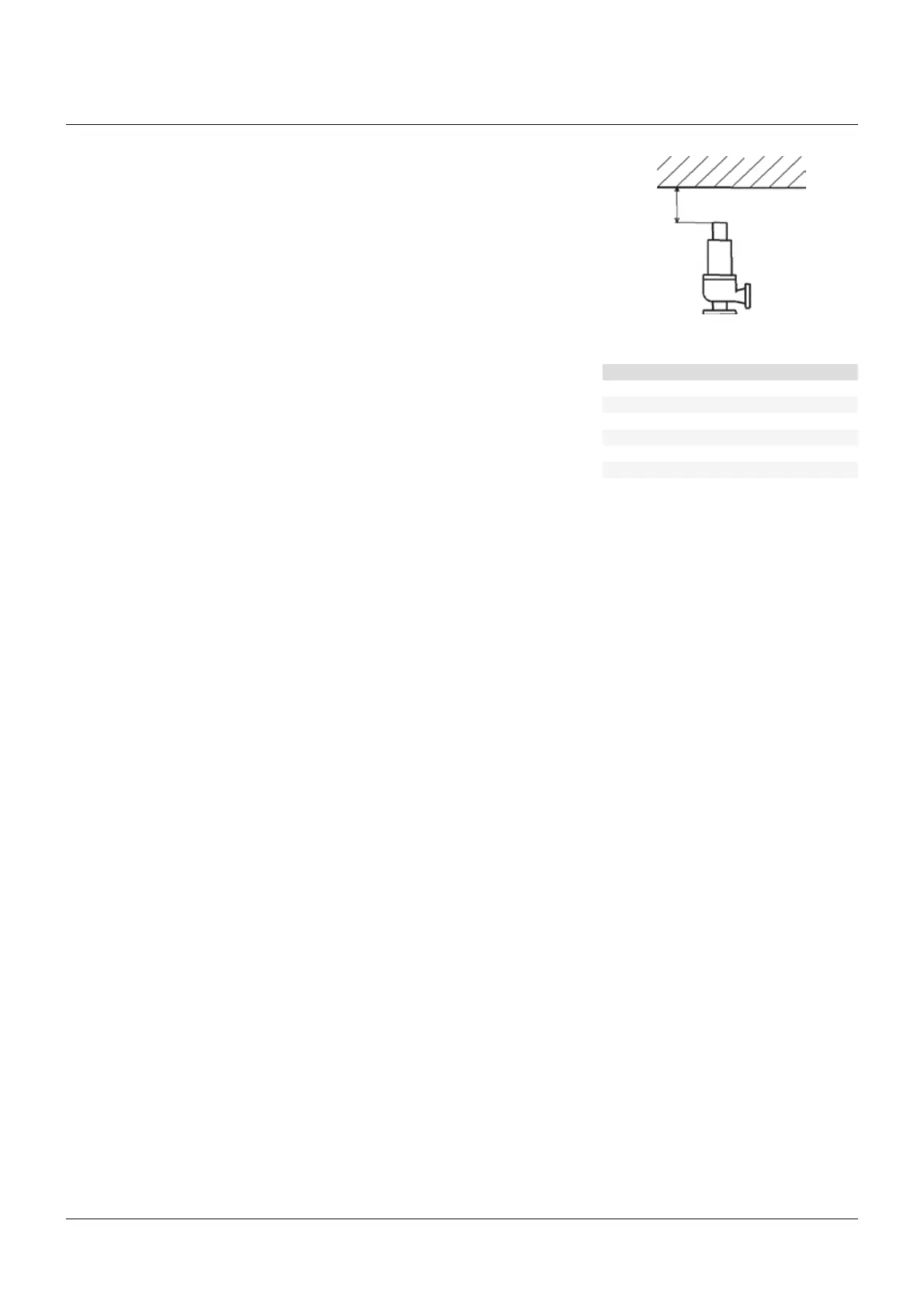
The installation zone must be easily accessible
for maintenance works. Required free space
above the safety valve see section Dimensions
In case of large safety valves provide for
additional space for lifting gears, at least
500mm.
Position of installation vertical, inlet from
below. Do not brace valve body when fastening;
if necessary compensate bearing of the
supporting brackets.
Lay line in such a way that neither static or
dynamic forces nor forces caused by thermal
expansion may be transferred to the valve body.
PLEASE NOTE
Stresses at the valve body may lead to leaking at
the valve seat!
3.3.2 Inlet line
If possible arrange safety valve directly at the
nozzle of the tank to be protected. Otherwise
lay inlet line between tapping point and safety
valve as short and as poor in resistance as
possible.
In no case the inlet line diameter must be
smaller than the inlet nominal size at the
safetyvalve.
The pressure loss in the inlet line must not
exceed 3% of the set pressure at the greatest
possible discharge quantity.
Check inlet line in regard of pressure vibrations
according to FBR 153 as far as possible.
DIMENSIONS
SKB
Overhead dimension X
A - G
300 mm
EA - JA
12"
H - R
700 mm
KA - RA
26"
S - Z
900 mm
TA
36"
3.3.3 Exhaust line
In no case the exhaust line diameter must be
smaller than the outlet nominal size at the
safety valve.
Back pressures in the exhaust line are
admissible up to 15% of the set pressure and
for safety valves with compensating piston
(SN 144) up to 50% of the set pressure, in
case there are no other restrictions, e. g. with
respect to the strength of the body connection
flange.
ATTENTION
Higher back pressures may lead to an unstable,
uncontrollable behaviour of the safety valve;
chattering or vibrating may destroy the valve seat,
the safety valve or the line and thus lead to failure
of the safety function or to shutdown of the plant!
At the deepest point the exhaust line must be
equipped with a drain which is large enough
to enable the discharge of minor leaks, e. g.
in case of untight valve seat. Particularly in
the open air exhaust line, valve body and drain
must be protected against icing and freezing,
e. g. by (electrical) trace heating; merely
insulating is not sufficient!
Do not exchange the drain connection G ¼” at
the valve body for the lock screw (44) at orifice
letters A40 and B40. Removing the lock screw
(44) may change the function of the safety valve!
ATTENTION
An icy, frozen or clogged exhaust line leads to the
failure of the safety function! Danger of explosion
in case of excess-pressure!
CAUTION
In case of several safety valves with one common
exhaust line, take special safety precautions for
disassembling of only one safety valve to exclude
danger in case of unintended discharge of other
safety valves!
Recommendation! Sound isolate exhaust line
and/or provide the same with silencer; in doing
so, regard allowable back pressure!
ATTENTION
A pressure loss higher than the closing pressure
difference may lead to an unstable, uncontrollable
behaviour of the safety valve; chattering or
vibrating may destroy the valve seat, the safety
valve or the line and thus lead to failure of the
safety function or to the shutdown of the plant!
For discharge of condensate in case of gases
and vapours, the inlet line must have a slope to
the tapping point of 15 degrees at least.
ATTENTION
Condensate at the inlet of the safety valve
changes the functional behaviour and may lead
to an inadmissible pressure increase. Danger of
explosion!
In case of liquids with temperatures higher than
the ambient temperature, the inlet line must
be assembled with slope to the safety valve, or
designed as a siphon-type bend in front of the
safety valve. Thereby, a heat transmission to
the safety valve is avoided which could impair
the tightness at the valve seat.
 Loading...