5
SEMPELL SERIES VSE/VSR FULL LIFT AND NORMAL SAFETY RELIEF VALVE
OPERATING INSTRUCTIONS
3.4 Pressure test
The response of the safety valve must be
prevented.
Either flange off the safety valve and close
the supply line with a blind flange or block
the valve. In case of welded-in safety valve a
pressure test insert can be used.
ATTENTION
In case of a blocked safety valve the test pressure
can amount up to 1.5 fold of the set pressure
without consultation with Sempell.
Turn in the blocking screw instead of the gag
plug (17) and tighten it securely by hand so that
the disc (4) is blocked in closed position. In case
of design with supplementary loading (SN 111)
screw off electric solenoid including cooling
spacer and replace it against a cap (13) with
blocking screw SN 100.
ATTENTION
After the pressure test, restore and check the
ready-to-operate state!
3.5 Commissioning
ATTENTION
At safety valves with weight load, Series VSE 4,
remove blocking screw before commissioning and
assemble gag plug (17) with gasket (40).
The safety valve is delivered ready to operate.
The set pressure is adjusted at works and
secured against unauthorized adjustments by
lead seal. Higher medium temperatures can
lower the set point at approx. 1% per 100°C
and ask for a readjustment under operating
conditions. Standard values see table in section
“Adjustment of the set pressure”.
3.6 Operational test
Function and reliability of the safety valves are
proved by the type test. Therefore operational
tests are generally not carried out in the plant.
This is only usual for steam boiler safety valves.
3.7 Discharge test
• Apply ear plugs.
• Slowly increase operating pressure in the
plant until the safety valve has fully opened.
• Lower operating pressure until the safety
valve closes.
In case of several discharge tests with hot
steam allow intermediate cooling down of the
safety valve as caused by heating of the spring a
slight decrease of the set pressure is possible.
ATTENTION
When discharging, some leaking medium may
escape at the open bonnet (8) in case of safety
valves Series VSE 1 / VSR 1. Danger of scalding by
hot steam!
3.3.4 Insulating
In case of hot medium insulate inlet line and
valve body. In case of gases and vapours
insulate inlet line and valve body very carefully
to avoid condensation.
ATTENTION
Condensate at the inlet of the safety valve
changes the functional behaviour and may lead
to an inadmissible pressure increase; danger of
explosion!
The spring bonnet and a possibly mounted
cooling spacer shall not be insulated as with
heated spring the set pressure decreases.
3.8 Adjustment of the set pressure
ATTENTION
A change of the lead sealed spring adjustment
must only take place in the presence of the
competent inspector.
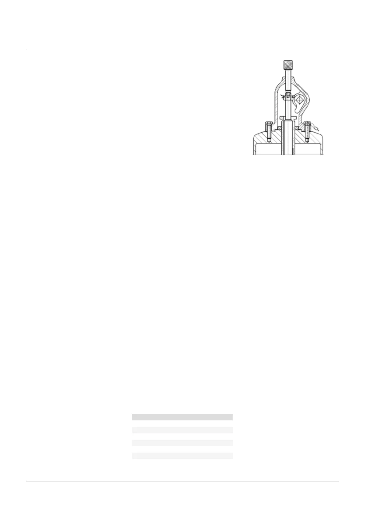
The adjustment of the set pressure takes place
on the test stand. If the set pressure is adjusted
in the plant, the pneumatic measuring device
A 143 should be applied as by means of this
device the set pressure can be adjusted without
increasing the operating pressure.
ATTENTION
Adjusting only with lowered pressure. At operating
pressure working on the tightening screw (11)
may lead to unintended response of the safety
valve. When discharging, some leaking medium
may escape at the spindle guide of the tightening
screw (11). Danger of scalding by hot steam!
Precision of the set pressure adjustment: ± 3%
Remove lead seal. Unscrew cap (13). Loosen
lock nut (28). For working at the tightening
screw (11) secure spindle (7) e. g. with a pin
against rotation as otherwise the valve seat
may be damaged.
Tighten tightening screw (11) (turn right):
setpressure higher
loosen tightening screw (11) (turn left):
setpressure lower
After the adjustment secure tightening screw
(11) with lock nut (28). Mount cap (13) and
leadseal.
Standard values for the change of the set
pressure in % for a quarter turn of the
tightening screw(11):
Orifice letter SKB Changes in %
AIV EAIV 10
AI-III, B, C EAI-III, FA 7
D-H GA-KA 4
J-M LA-NA 3
N-R PA-RA 1.5
S-W TA 1
X-Z 0.5
 Loading...