EasyManua.ls Logo

Senergy SEN803FCT-RC/2 - User Manual

Senergy SEN803FCT-RC/2
7 pages
Print Icon
To Next Page IconTo Next Page
Loading...
SEN803FCT-RC/2 FAN COIL THERMOSTAT
Applications : Control FCU with Cooling/Heating Mode, 03-Fan Speed
INTRODUCTIONS-----------------------------------------------------------------------------------------
The 803FCT/2 Series of Digital thermostats are
specifically designed for control of commercial
heating and cooling equipment such as rooftop
units (with and without economizers), heat pumps,
and fan coil unit. The large LCD display is easy to
set up and program through the use of a plain text
menu driven backlit display that walks the user
through the programming process. Additionally, the
803FCT/2 has over four configurable parameters,
enabling the thermostats to adapt to a variety of
applications..
SPECIFICATION-------------------------------------------------------------------------------------------
Power Supply…………………………...….....100~240VAC,50/60Hz
Fan speed Relay………………………….......2A
Cooling/Heating Relay…………………….....0.5A
Room Temperature Scale…………………...5
o
C to 35
o
C
Dimensions…………………………….…...…86x86x15mm( 3.38x3.38x0.6inch)
FEATURES AND BENEFITS---------------------------------------------------------------------------
Large LCD display with backlight
Temperature adjustments are simple with the large up-down arrows
Display shows both set points and room temperature simultaneously
Maintains the temperature to within 1 degree set point
Auto fan with adjustable 3-fan speed
Permanent user setting retention during power loss, no batteries are required
Input room card for energy saving mode Room Card Function
Question and Answer IconNeed help?

Do you have a question about the Senergy SEN803FCT-RC/2 and is the answer not in the manual?

Summary

Introductions

Specifications

Features and Benefits

Front View and Controls

Thermostat Buttons and Switches Overview

Identifies and lists all buttons and switches on the thermostat's front panel.

Thermostat Display Area Icons

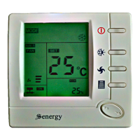
Explains the meaning of various icons and information displayed on the thermostat screen.

Thermostat Installation Guide

Operational Checks and Diagrams

Wiring Diagrams

Illustrates different wiring configurations for the thermostat system.

Fan Operation Modes

Details how fan speed is selected and adjusts automatically based on temperature.

Heating System Operation

Explains how to activate and control the heating system using the thermostat.

Cooling and Sleep Mode Operations

Cooling System Operation

Guides on activating and controlling the cooling system via the thermostat.

Sleep Mode Functionality

Describes the automatic temperature adjustments during sleep mode for comfort.

Room Card Energy Saving Mode

Explains how the room card enables energy saving and temperature control.

Programming and Configuration Settings

Temperature Adjustment

Allows calibration of the displayed room temperature by +/- 3 degrees.

Maximum Temperature Limitation

Sets the upper limit for the desired temperature, adjustable from 26°C to 37°C.

Minimum Temperature Limitation

Sets the lower limit for the desired temperature, adjustable from 5°C to 24°C.

Fan Mode Selection

Configures fan operation to be automatic or manual based on heating/cooling calls.

Overview

The SEN803FCT-RC/2 Fan Coil Thermostat is a digital thermostat designed for controlling commercial heating and cooling equipment, specifically fan coil units (FCU) with cooling/heating modes and three-fan speed control. It is suitable for various applications, including rooftop units (with or without economizers) and heat pumps.

Function Description:

The thermostat provides precise control over fan coil units, allowing users to manage both heating and cooling functions. Its large LCD display and menu-driven backlit interface simplify setup and programming. The device offers configurable parameters to adapt to different application requirements. Key functions include temperature adjustment, fan speed control (HI, MED, LOW, AUTO), and a sleep operation mode for energy saving. It also features a room card function for energy-saving mode, where the thermostat can automatically adjust settings when a room card is inserted or removed.

Important Technical Specifications:

  • Power Supply: 100~240VAC, 50/60Hz
  • Fan Speed Relay: 2A
  • Cooling/Heating Relay: 0.5A
  • Room Temperature Scale: 5°C to 35°C
  • Dimensions: 86x86x15mm (3.38x3.38x0.6 inches)

Usage Features:

  • Large LCD Display with Backlight: Provides clear visibility and ease of use, even in low-light conditions.
  • Simple Temperature Adjustments: Utilizes large up-down arrows for intuitive temperature setting.
  • Simultaneous Display: Shows both set points and actual room temperature concurrently.
  • Accurate Temperature Maintenance: Maintains the temperature to within 1 degree of the set point.
  • Auto Fan with Adjustable 3-Fan Speed: Allows for automatic fan speed adjustment based on temperature difference or manual selection of high, medium, or low speeds.
    • In AUTO speed mode, the fan speed changes according to the difference between room temperature and set temperature:
      • HI speed: If room temperature is 3°C higher (cooling) or 3°C lower (heating) than the set temperature.
      • Medium speed: If room temperature is 2°C-3°C higher (cooling) or 2°C-3°C lower (heating) than the set temperature.
      • Low speed: If room temperature is 0°C-2°C higher (cooling) or 0°C-2°C lower (heating) than the set temperature.
  • Permanent User Setting Retention: Settings are retained during power loss without requiring batteries.
  • Room Card Function (Energy Saving Mode):
    • When the room card is removed, the thermostat enters an energy-saving mode (auto mode) with fixed temperature settings (25°C for cooling, 18°C for heating), and temperature adjustment is disabled.
    • When the room card is inserted, temperature adjustment and other functions become available.
  • Sleep Mode Operation:
    • Activates an 8-hour energy-saving program that gradually adjusts the set point temperature.
    • In cooling mode, the set point temperature is raised by 1°C after 1 hour and by 2°C after 2 hours, maintaining this until the 8-hour timer expires, then reverting to the original setting.
    • In heating mode, the set point temperature is decreased by 1°C after 0.5 hours, by 2°C after 1 hour, and by 3°C after 2 hours, maintaining this until the 8-hour timer expires, then reverting to the original setting.
  • Configuration Menu: Allows users to customize thermostat operating characteristics, including:
    • Temperature Adjustment (Item 1): Adjusts room temperature display by -3 to +3 degrees.
    • Maximum Temperature Limitation (Item 2): Sets the maximum allowable temperature between 26°C and 37°C (default 37°C).
    • Minimum Temperature Limitation (Item 3): Sets the minimum allowable temperature between 5°C and 24°C (default 5°C).
    • Fan Mode (Item 4): Selects "On" (fan runs continuously) or "OFF" (fan stops when there is no call for heat or cool).
    • Active Room Card Mode (Item 5): Configures how the room card input affects energy saving:
      • "SC": Energy saving mode activated when dry contact is closed.
      • "OC": Energy saving mode activated when dry contact is open.
      • "00": Energy saving mode disabled.
    • Energy Saving Setpoint in Cooling Mode (Item 6): Sets the energy-saving cooling temperature between 25°C and 30°C (default 25°C).
    • Energy Saving Setpoint in Heating Mode (Item 7): Sets the energy-saving heating temperature between 10°C and 18°C (default 18°C).
    • Select Mode (Item 8): Chooses between "COOL," "ALL," or "HEAT" modes.

Maintenance Features:

  • Installation:
    • Safety Warning: Always turn off power at the main service panel before installation to prevent electrical shock.
    • Compliance: Installation must conform to local and national building electrical codes and ordinances.
    • Procedure:
      1. Remove the control panel from the power base.
      2. Connect wires to terminal screws on the power supply module according to the wiring schematic.
      3. Push the power base into an 86mmX86mm conduit box.
      4. Mount the power base to the wall using two screws, ensuring it is level.
      5. Snap the control panel back onto the power base.

The SEN803FCT-RC/2 thermostat is a comprehensive solution for efficient and user-friendly control of fan coil units in commercial environments, offering a blend of functionality, energy-saving features, and ease of installation.

Senergy SEN803FCT-RC/2 Specifications

General IconGeneral
BrandSenergy
ModelSEN803FCT-RC/2
CategoryThermostat
LanguageEnglish