MANUALE D'INSTALLAZIONE RAPIDO
SHORT INSTALLATION MANUAL
MT4359 rev1.doc 08/07/2019 Page 2 of 4
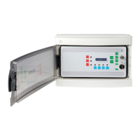
Aprire il pannello frontale della centrale ruotando la
serratura su UNLOCK.
Scollegare il morsetto CN10 che collega i cavi
d'alimentazione della scheda all’alimentatore sul fondo
del box; scollegare anche il morsetto JP15 dei segnali
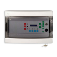
di controllo alimentatore. Richiudere il pannello
frontale girando la serratura su LOCK.
Togliere le 4 viti poste a lato del pannello e rimuovere
la parte frontale della centrale.
Ora è possibile forare la custodia posteriore per
consentire l'entrata dei cavi.
Raccomandiamo di eseguire l'entrata dei cavi
preferibilmente nella parte inferiore, utilizzando un
pressa-cavo idoneo IP65 per poter mantenere lo
stesso grado di protezione della centrale.
Fissare la parte posteriore della centrale a parete
mediante le staffe di fissaggio riportate in figura.
UNLOCK the control panel front door and open it.
Disconnect the CN10 terminal, which connects the
main PCB of the control panel to the power supply on
the back side of the box, and the JP15 terminal for
power supply signal controls.
Close the front door and LOCK it again.
Unscrew the four screws placed close to the panel and
remove it.
Now it is possible to drill the rear panel to allow the
cables entrance.
We would recommend having cables entering from the
lower side.
Make sure you are using an adequate IP65 rated cable
gland to assure the box ingress protection is not
compromised.
Wall fix the rear panel through the mounting brackets
detailed in the picture.
Riposizionare il pannello frontale tramite le 4 viti
rimosse in precedenza.
Girare su UNLOCK, aprire lo sportello frontale e
ricollegare i morsetti CN10 (alimentazione) e JP15
(segnali controllo).
Fasten the front panel by using the 4 screws you
previously removed.
UNLOCK the front door and connect again the
terminals CN10 (power supply) and JP15 (control
signals).
Procedere con il collegamento dei rivelatori
Proceed with the gas detectors connection
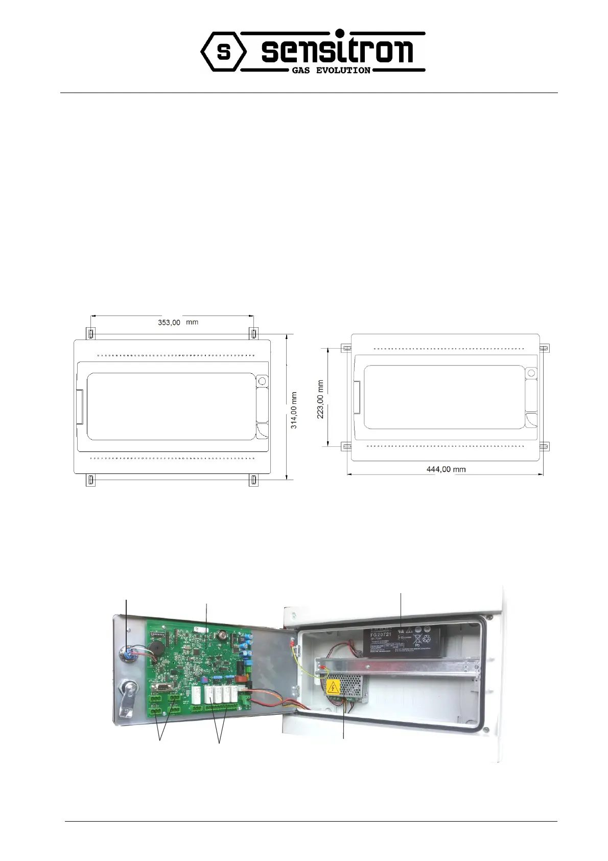
1-alimentatore / power supply
2-batteria 12V 7Ah / battery 12V 7 Ah
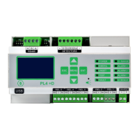
3-scheda elettronica / main electronic board
4-morsetti rilevatori (1-4) / detector (1-4) terminals
5-relè e morsetti / relays and terminals
6-chiave elettronica / electronic key
 Loading...