Do you have a question about the Sensitron ST.PL4+ and is the answer not in the manual?
Details on power supply, consumption, inputs, outputs, display, and conformity standards.
Identification and rating of fuses for main supply and battery backup.
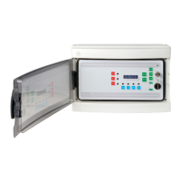
Instructions for physically mounting the control panel, including drilling and cable entry.
Diagram and description of the main PCB, connectors, jumpers, and terminal blocks.
Guide to selecting the display language using jumpers on the microprocessor board.
Details on connecting the optional expansion module for additional detectors and outputs.
Explanation of the automatic self-test routine for verifying microprocessor and safety functions.
Procedure for connecting the 220Vac main power supply cable to the terminal board.
Information on connecting 4-20mA detectors, including cable type, shielding, and maximum distance.
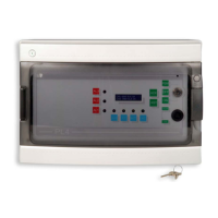
Description of status LEDs and push buttons on the control panel's front interface.
Procedure for connecting backup battery and performing first power-on and system initialization.
Normal operating mode with detector signals managed and relays active.
Panel indication of alarm states (A1, A2, A3) with LEDs, buzzer, and reset procedures.
Panel indication of fault states (FLT) with LED, buzzer, and reset procedures.
Mode where detectors are managed, but relay outputs are not activated (key switch OFF).
Mode for parameter configuration, indicated by FLT LED and periodic beeps.
Indication of low battery condition with BATT/FLT LEDs and specific display message.
Indication of over-range input signal with FLT, blocked readout, and reset procedure.
Step-by-step example for programming a flammable gas detector input, including range and alarm thresholds.
Guide for programming Oxygen detector inputs, setting range and depletion/enrichment thresholds.
Configuration of output relay behavior (latched, direct, delayed) for alarm events.
Procedure to restore all settings to factory defaults, erasing custom configurations.
| Brand | Sensitron |
|---|---|
| Model | ST.PL4+ |
| Category | Control Panel |
| Language | English |