© Sensortech Systems, Inc. 2016 Page 3 of 16 Rev.7-2016
ST-2200 Sensor System Installation Guidelines
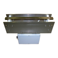
Locating the Sensor:
Select a location to install the ST-2200 Sensor where the board will remain flat over the Sensor
for the full length or width of board travel over the Sensor.
Avoid locations where the air gap between the board and Sensor may change during board travel
due to changing slope or roller height on Dry End Transfer conveyor or Takeoff Cascade.
Preventing board bounce while arriving, travelling over and leaving the Sensor results in the best
measurement accuracy. In addition, it is desirable to prevent a board impacting the Sensor due to
board bounce or changing angle of approach or departure from the Sensor.
The spacing between the top of the Sensor to the bottom of a board is critical for good
measurement accuracy. The specification for the air gap between the board and Sensor is 0.25
inches (6.35mm). A typical ST-2200 Sensor is installed on a Mounting Beam centered between
level rollers 12-18 inches (30-45cm) apart.
When measuring board traveling over the Sensor for the full length of the board, the
recommended minimum distance from the end of the Take-off Cascade is calculated as follows:
Sensor Location = Longest Board Length + 1 Roller (from the Take-off Cascade)
i.e. if the Longest Board Length = 14 feet (4.3m) and the roller spacing is 12-18 inches (30-
45cm) then the mounting beam for the Sensor should be installed greater than 15 feet
(4.6m) from the end of the Take-off Cascade.
When measuring board traveling over the Sensor for the full width of the board, the
recommended minimum distance from the Inverter on the Dry End Transfer is calculated as
follows:
Sensor Location = Widest Board Width + 1 Roller (from the Inverter)
i.e. if the Widest Board Width = 4 feet (1.22m) and the roller spacing is 12-18 inches (30-
45cm) then the mounting beam for the Sensor should be installed greater than 5 feet
(1.5m) before the Inverter.
 Loading...