© Sensortech Systems, Inc. 2016 Page 4 of 16 Rev.7-2016
Preparing for the installation:
1. Fabricate and install a height adjustable beam for installing the Sensor after the kiln or dryer
between the rollers. Ensure the adjustment range allows the Sensor to be positioned at 0.25
inch (6.35mm) spacing from bottom of board when resting on rollers.
2. Run a 10-16 AWG Earth Ground wire from local ground source to Sensor mounting location.
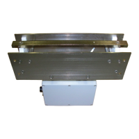
3. Mount the Processor Unit in the desired location per supplied drawings (see Figure 7 & 8). It
is recommended to mount the Processor Unit near the Sensor mounting location and run the
4-20mA cable for moisture output to the control room Process Controller / PLC.
4. Install conduit or cable run for Processor Cable from the Sensor to the Processor Unit.
5. Provide AC plug receptacle for main AC power to Processor Unit (110-240VAC 20A Service).
6. Run an Earth Ground wire from local ground source to Processor Unit mounting location.
7. Install any external equipment / PLC cabling to Processor Unit terminal block signals (RS-232
serial link, 4-20mA loop, external alarms, product detectors, etc.).
Important:
Do not mount the Sensor with attached Sensor Electronics Unit where excessive heat
transfer will occur. Ensure that Sensor is located away from exhaust gases venting from
the dyer to prevent measurement drift or electronics failure due to the attached Sensor
Electronics Unit over-heating.
Provide an Earth Ground for the Sensor. Ensure a side plate of the Sensor is connected to
local Earth Ground. Add a 10-16 AWG direct wire connection from the Sensor with
attached Sensor Electronics to a local Earth Ground potential. Ensure sensor frame is
grounded to process frame or conveyor frame, etc. This is not a safety requirement, but
may influence instrument performance.
 Loading...