NO
1A 24 V~
NC
DAL 1965
Pag. 9/10
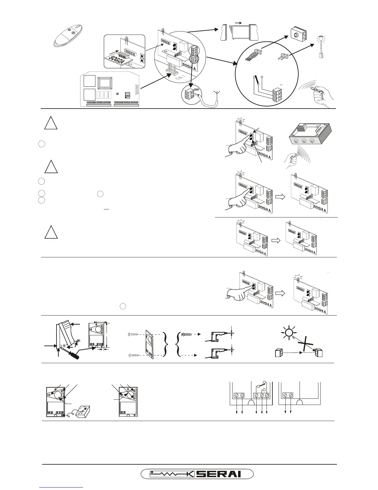
F1 F2 F3 F4
CR/14
CN 1
ANTENNA
!
LED ON
LED OFF
!
!
LED OFF
NO!
Ø 6mm
Ø 3,5mm
87 mm
29 mm
19 mm
TX RX
PHOTOCELLS P/94
ALIGNING
ELECTRICAL CONNECTIONS
ADJUSTING SCREWS; RECEIVER LED IS ON ONLY
WHEN THE LIGHT BEAM IS ALIGNED
3,5V- MIN!
(LED = ON)
LED
CONTACT STATE IS RELATED TO
ALIGNED LIGHT BEAM CONDITION
RECEIVER TRANSMITTER
(24V@) (1A / 24V@) (24V@)
TECHNICAL DATA
Power supply 24V@ ±10%
TX load 28mA a 24 V-
50 mA a 24 V~
RX load 17 mA a 24 V-
40 mA a 24 V~
External range 25 m
Indoor range 50 m
N. 2 relais 1 switch 1A / 24 V@
Temperature -10 ÷ +60 °C
Dimensions/weight 58 x 104 x 44 mm / 220 g
LED
RADIO CONTROL 433,92 MHz
MEMORY EXPANSION
FROM N°40 TX TO N°834
1° CHANNEL
2° CHANNEL
MONOSTABLE
FUNCTION
BISTABLE
FUNCTION
LIGHTS
ELECTRIC LOCK
RADIO CARD PROGRAMMING
ATTENTION: before using each minitransmitter it is
necessary to execute the procedure for the receiver
programming
1 keep pressed the button of the chosen channel for 1 sec., the led
will flash and then it will remain fix.
ATTENTION: do not keep pressed the button for 5 sec.
or more, the already stored codes will be erased.
4 keep pressed the button on the receiver for 1 sec in order to exit
from the programming or wait 2 minutes the red led has to switch
off.
when the number of available codes per canal -40 or
834- is exhausted the receiver exit automatically from
the programming
PROGRAMMING RESET
if you want to reset the programming of one of two channels,
keep pressed the button of the relevant channel for 5 sec.the red
led will light up fix.
HOW TO ADD NEW TRANSMITTERS
repeat the operations from the 1 point.
2 press the transmitter in order to send the signal, the led will flash
and then it will remain fix: stored code
3 repeat the operation 2 for storing other transmitters
1° CHANNEL
2° CHANNEL
KIT/18F-18H-25H I E
 Loading...