SPECIFICATION
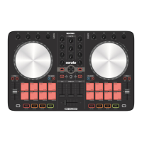
FUNCTION
FX1~3-------------------------------------------To turn on the sound effect
PITCH - +---------------------------------------To temporarily adjust the speed for beat matching
BEATS------------------------------------------To adjust the beat for sound effect
PAD MODE 1~2 ----------------------------To switch between 2 PAD MODE
PAD 1~8-----------------------------------------Tap them to perform Beat Loop and Hot Cue
SYNC--------------------------------------------To make the BPM of two playbacks the same
CUP----------------------------------------------To return to CUE point and instant play
Play/Pause---------------------------------------To control a play or pause mode of its belonging deck
CUE1~2------------------------------------------It's for setting and play 2 hot cues
CUE----------------------------------------------To set a master Cue memory as a start point
SHIFT--------------------------------------------It switches between the first mapping and the second mapping
SAMPLER FADER----------------------------Advance the fader for required sample volume
STANDARD
Output level…………………....................1.0±0.2 Vms(1KHz 0dB)
S/N Ratio……………………....................More than 80 dB
Frequency response………………………20Hz~20KHz
±
2dB
Dynamic range………………....................More than 80dB
Channel separation…………......................More than 80dB
Channel balance…………………………...
±
1dB
Harmonic distoryion…………....................Less than 0.05%