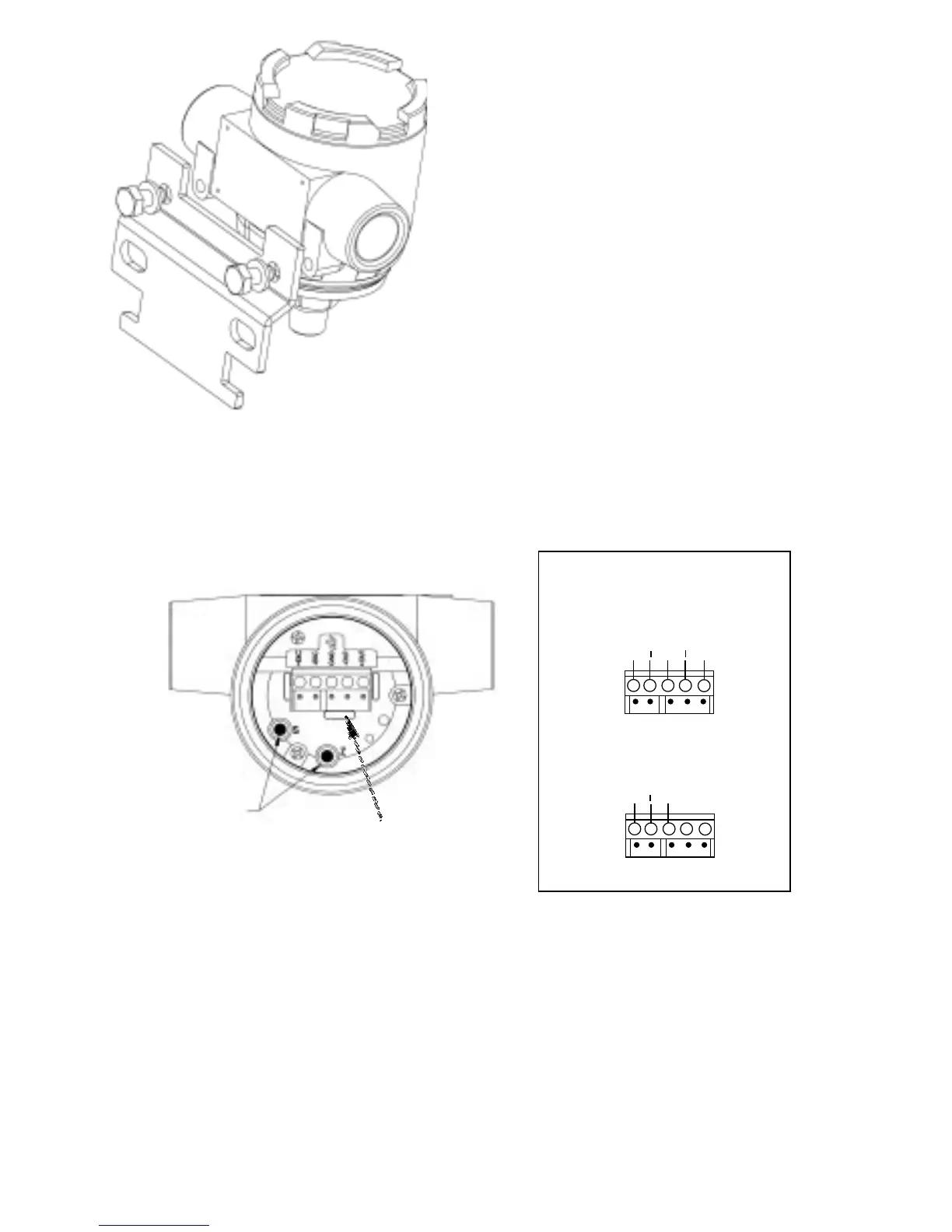
+ EXC
EXC
GND
OUT
+ OUT
Voltage Connections
Current Connections
Screw Terminal
Designations
Diagram 1
+ EXC
EXC
GND
Diagram 2
Removable
Zero/Span
Access Plugs
Removable
Terminal Block
Connector
5
3.1 Voltage Output Units
The Model 256 is a 3-wire circuit. The -EXC and -OUT are commoned on the
circuit. The 256 can operate from a 12 to 28 VDC excitation. The 256 has a 0.1-
5.1 VDC output.
+ Excitation; connect to 12-28 VDC power supply
+ Output; connect to controller or monitor
– Output; connect to controller or monitor
– Excitation; connect to return of 12-28 V power supply
GND Connect to system or earth ground
The Model 256 can be wired as a three wire device by connecting – output,
excitation and shield to a common ground. However, accuracy will be reduced
with increase in lead resistance.
2.6 Mounting Accessories
The Model 256 is provided with a bracket and
two hex bolts for mounting and a 1/2” NPT plug
for the unused conduit opening. The bracket is
suitable for mounting with a U-bolt or a band
clamp. There are 1/4-20 UNC threaded holes on
the back of the 256 transducer for direct mounting
and/or grounding.
3.0 ELECTRICAL INSTALLATION
Wiring is through a 1/2” conduit opening. Remove the
screw cover to access the removable wiring terminal
block connector. The terminal block connector version
has five terminals for wiring +EXC, -EXC, GND, -OUT, and
+OUT (see Diagram 1).
Remove the terminal block connector to facilitate wiring to screw terminals.
Refer to the terminal block connector label for terminal designations. (See
Diagram 2 for screw terminal designations.) After wiring, plug connector back
into pin socket and neatly tuck all wiring into wire recess cavity.