instructions covering the valve, positioner and any
accessories. Where the valve is operated by electric,
hydraulic or electro hydraulic actuation, follow the IOM
instructions provided by the actuator manufacturer.
Only persons qualified through training and or experience
should install, operate and maintain this product. In case of
questions about these instructions or the valves please
contact the nearest Severn Glocon office before proceeding.
Instructions in the following paragraphs describe the
installation procedures for the actuator. Instructions not
included are to be performed in accordance with standard
industry acceptable practises as may be required by local
codes, specifications and or regulations. Users should refer
to BS 6683 “Guide to installation and use of valves”.
Storage
Unless specifically specified by the contract, the actuator (or
valve and actuator) are packed for indoor storage at job site.
For short term storage the actuator or valve and actuator,
should be installed in a fire resistant weather tight and well
ventilated building. The equipment should be kept at a
temperature of –20F (-29deg.C) to +120F (48deg.C). The
area should be constructed and situated so that it will not be
subjected to flooding; the floor should be similarly level, firm,
protected and well drained. Actuators and valves should be
on pallets or shoring to permit air circulation.
For longer storage, a corrosion preventative should be
considered that is compatible with the process fluids.
Further advice should be sought from Severn Glocon.
Handling
Applicable codes regulations and industry practices must be
followed when handling or lifting valves. Care should be
exercised to protect instrumentation / ancillary equipment.
Severn Glocon lifting guidelines are available on request.
Installation
Make sure adequate overhead clearance exists when
installing the actuator. Minimum clearance is 150mm. It is
usual to use the actuator with a suitable valve positioner. If
this is the case, the air supply and instrument signal
connections must be connected as per the positioner
manufacturer’s instructions.
WARNING: Do not exceed the recommended air supply
pressure shown on the Severn Glocon specification sheet,
as injury to personnel or damage to equipment may occur.
The use of an air filter regulator on the air supply line is
recommended. Instrument quality air is required for
operation of the actuator and any ancillaries fitted.
The weight of the actuator valve assembly should be taken
into consideration when mounting on to a valve. Supports
may be required depending on the actuator orientation.
Actuator Removal and Fitting to Valve
Two types of fitting arrangement for actuators are possible.
Smaller actuators may be fitted by a half ring yoke design
method with either lock nut or stem clamp between stem
and actuator piston. Alternatively, all sizes of actuators may
be fitted by a bolted yoke and stem clamp design method.
IMPORTANT: See warnings on page 1 in regard to isolation
of items to be worked on and carry out safe isolation before
beginning work.
WARNING: Escaping air can cause personal injury, avoid
skin contact and wear eye protection. Take care to correctly
support any parts being lifted. Take care to remove any
linkage mechanisms before starting work to avoid damage.
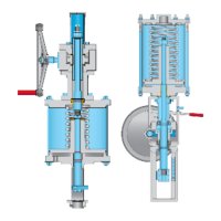
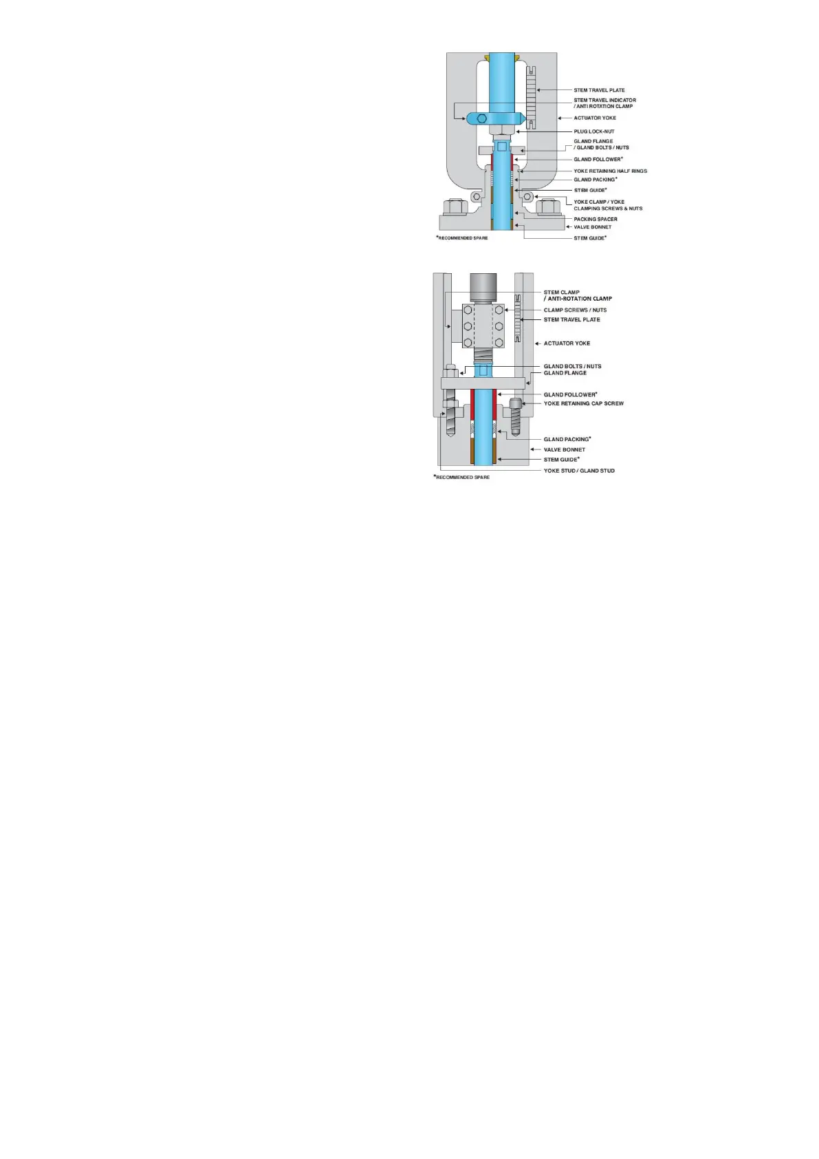
Half Ring Yoke Design showing lock nut connection
(Actuator sizes
P25, 50 and 100)
Note: This design
may be fitted with
a stem clamp
instead of the lock
nut design. In this
case read relevant
sections of both
design options for
fitting
Bolted Yoke showing Stem Clamp Design
(All Actuator Sizes)
NOTE Yoke Fixings
and Gland Flange
Studs shown 90
degrees out of position
for clarity on Bolted
clamp design
Actuator Removal (Half ring fixing method).
Connect suitable slings to support the actuator weight. For
air fail actuators the valve plug/actuator stem should be
moved to approx. 50% open by means of air. This can be
achieved by using a temporary air line with a manually
controlled pressure regulator and connected to the lower air
port (spring close model) or the upper air port (spring open
model) in the actuator. With the valve in this position, the
plug locknut can be loosened, remove the yoke clamps and
spin the actuator off the valve plug. Caution; Do not allow
plug to rotate during unscrewing. When the actuator
disconnects from the plug, the plug may drop onto the seat
position; take care not to trap fingers. If the plug does not
drop, push the plug to the closed position. Remove the plug
lock nut, and gland flange. Push the actuator downwards
towards the valve body to allow removal of the two yoke
retaining half rings from the groove in the top of the valve
bonnet. The actuator can now be lifted clear of the valve
and all air vented from the actuator. Caution: This will cause
the actuator piston rod to move to the air fail position.
Actuator Fitting (setting the correct plug position)
Before fitting the actuator, extend the piston rod to the
maximum extended position and mark location on the yoke.
Connect suitable slings to support the actuator weight for
both air fail actions. For air fail close type lower the actuator
on to the valve body; during this operation loosely fit the
gland flange and plug lock nut. By rotating the actuator onto
the plug stem it will then be possible to fit the yoke retaining
half rings. Once these have been fitted rotate the actuator in
an anticlockwise direction until the half rings are a snug fit in
the yoke. The yoke clamps, the gland bolts and nuts can
now be fitted. Caution; During this process ensure the plug
is not driven hard into its seat or is allowed to rotate.
For air fail open type actuators use a temporary air line and
manual regulator as above to move the actuator down
slowly so as to be able to rotate the actuator onto the plug
stem. See prior caution notes. Relieve all air pressure and
disconnect. By screwing the actuator onto the plug it will be
possible to allow the yoke to be pushed down towards the
valve body and the yoke retaining half rings can be fitted.
Allow the actuator to rise after fitting to hold these rings in
place then fit the yoke clamps, gland bolts and nuts.
 Loading...