Setting the plug to its seating position.
With Actuator Piston Rod fully extended, (this can be seen
by the marks made earlier on the yoke) and with the plug
set fully on the seat, the actuator piston should extend to a
position short of the mark by approximately 1.5 - 3mm.
Adjust the plug to achieve this position by screwing the
actuator in or out. Do not rotate the plug. Move the actuator
up and down slowly to ensure smooth operation. Set the
plug lock nut. This position may need to be adjusted again
later depending upon the type of positioner when fitted.
Fully stroke the actuator to ensure smooth operation. NOTE:
When installing new or re-fitting the actuator, refer to valve
IOM detail on appropriate tightening of packing gland.
Actuator Removal (Bolted Stem Clamp fixing method)
Set the actuator just off its valve seat by use of a temporary
air line/regulator as above. Undo the clamp screws and nuts
to separate the actuator piston from the plug stem (the
piston may move up/down and in rare cases contact the
plug stem). The plug position may have to adjusted slightly
so as to allow the split clamp to release from its thread.
Air in the actuator can now be slowly released. Loosen the
gland bolts and gland flange. Loosen the yoke retaining cap
screws by approximately. 6mm to ensure spring force is fully
relaxed (actuator rocks easily). The actuator can now be
removed taking care not to damage the valve plug.
Actuator Fitting (setting the correct plug position to ensure
proper seating force is applied during normal operation.)
Fitting follows the reverse methodology of removal, but plug
should be set to its on seat position. Operate the actuator
piston down to its fully extended position (it should not hit
the top of the plug stem). Do not rotate the plug. The piston
should then be raised by approximately 6mm before fitting
the clamp. Adjust the stem position to ensure the threads
mesh fully and fit the other half of the clamp tightly. Fully
stroke the actuator to ensure smooth operation.
Pre-Operation
The actuator and control valve positioner must be set to
correctly close and seat the valve so as to not give rise to
premature trim degradation. If a manual handwheel override
is provided in the actuation system, ensure this is in the
disengaged or neutral position. Clean the actuator shaft of
any foreign matter. Always use correct tools including the
use of torque wrenches to assure bolts are not over
tightened during any checks carried out.
Operation
In operation, ensure that the actuator operates smoothly
and that there is no juddering or unusual motion. If the
actuator exhibits any strange behaviour, please contact your
nearest Severn Glocon representative immediately.
IMPORTANT: For all valve adjustments refer to relative IOM
instructions. If any doubts exist, contact SEVERN GLOCON
Maintenance
Actuator parts are subject to normal wear and tear and must
be inspected and replaced as necessary. Inspection and
maintenance frequency depends upon the severity and
importance of the service.
WARNING: The actuator may be spring loaded. Use care to
follow normal safety procedures when removing actuator
casings and end caps. When turning off the air supply the
actuator will move to its fail-safe position. Keep personnel
away from the moving parts of the valve and actuator during
this process to avoid personnel injury. The actuator may
move very quickly during this process.
Spare Parts
Whenever an actuator is disassembled, it is recommended
that all soft parts are replaced. These are consumable parts.
Troubleshooting
Jerking or sticky stem travel
AUXILIARY HANDWHEELS AND LIMIT STOPS
Top-mounted, Continuously Connected Handwheels
Fitted on
Actuators
Size P25,
50 and 100
Advanced Maintenance
The top-mounted, continuously connected hand-wheel is
totally, enclosed, so only checking for general condition is
required. However, disassembly may be necessary if the
mechanism fails. When reassembling the handwheel, be
sure to clean and lubricate the screw and drive nut with a
multi-purpose grease and replace ‘O’ rings with new.
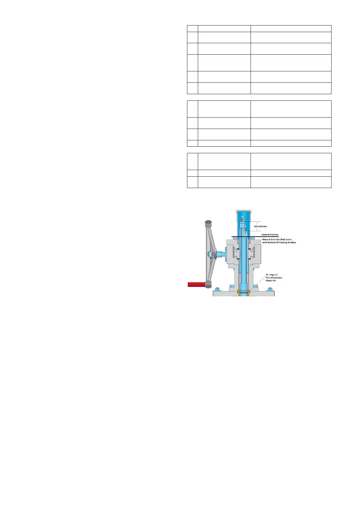
IMPORTANT: After operation of the override it must be
returned to the neutral position for automatic operation
(shown by manual override shaft level with the bottom of the
viewing window in the hand-wheel end cover tube (6).
Operation
If a pneumatic failure occurs, or if manual control of the
valve is desired, the unit can be operated as follows:
1. Set the three-way bypass valve (located on the
pneumatic supply line to the positioner) to “Hand” to vent the
air pressure from the actuator. NOTE: a three-way valve is
installed in the supply line only when there is no lock-up
system or volume tank. On volume tank or lock-in place
systems, the bypass valve is located between the top and
bottom cylinder ports. However, on some pneumatic circuits
the single three-way bypass valve may be substituted by
two two-way manual valves. Consult the pneumatic circuit
supplied with the actuator documentation.
WARNING: By venting the air, the actuator will move to the
fail safe position, this may be fast. Please keep away from
moving parts including the positioner linkage to avoid injury.
 Loading...