2. To open the valve, turn the hand-wheel counter-clockwise
to retract the plug. To close the valve, turn the hand-wheel
clockwise to extend the plug.
4. To return the valve to automatic control, return the hand-
wheel nut to the ‘neutral’ as shown by the handwheel
position indicator and set the three-way bypass valve (see
previous NOTE) to ‘auto’. The neutral position is indicated
when the top of the screw aligns with the marked line on the
cap liner (see diagram).
5. Adjusting the hand-wheel nut to a position other than
neutral provides a limit open or close stop function
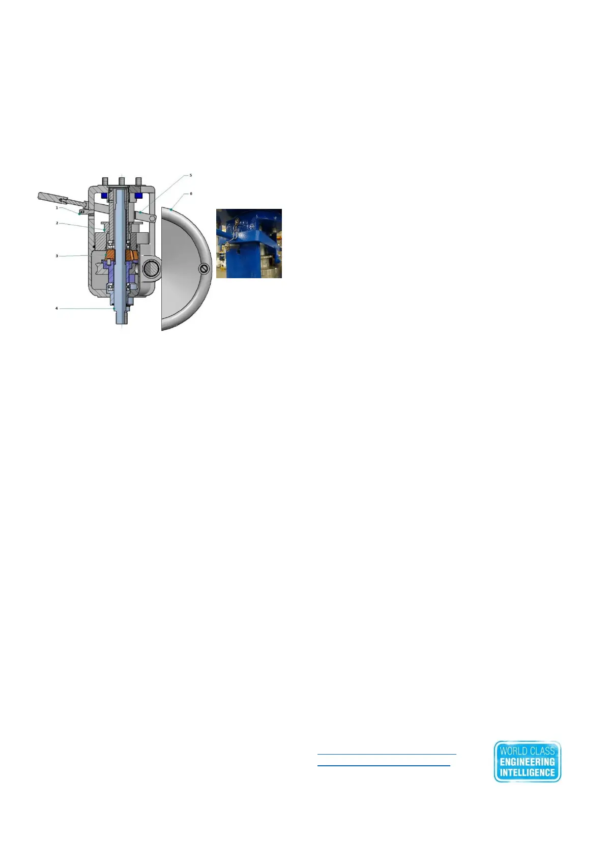
Declutchable Handwheels
Size P100,
and 200
Pin and
lever in auto
position
(Lever Up)
Advanced Maintenance
This is an enclosed unit. For long life, it is important to keep
a coating of multi-purpose grease on the acme threads and
engaging collets at all times. A grease point is provided and
a multi-purpose grease should be pumped into the unit
periodically. Oil can be applied to the hinge pins, the
operating lever and the bearings on handle mechanism.
WARNING: If the mechanism has been operated incorrectly
it is possible to strip the acme threads on the actuator piston
rod and replacement parts will be required.
Operation
If an air failure occurs, or if manual control of the valve is
desired, the handwheel override can be operated as follows:
1. Turn off the pneumatic supply. This is carried out by
operating the three-way bypass valve (located on the air
supply line to the positioner) to “Hand” to vent the air
pressure from the actuator. NOTE: three-way valves are
installed in the supply line only when there is no lock-up
system or volume tank. On volume tank or lock-in place
systems, the bypass valve(s) is located between the top and
bottom cylinder ports. However, on some pneumatic circuits
the single three-way bypass valve may be substituted by
two two-way manual valves. Consult the pneumatic circuit
supplied with the actuator documentation.
WARNING: Venting air will move actuator to the fail safe
position, this may be fast & personnel must keep away from
moving parts including the positioner linkage to avoid injury.
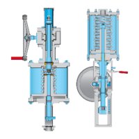
2. After isolating the pneumatic supply remove the operating
lever locking pin (1), from its hole beneath the operating
lever assembly (5). Do not lose this pin (it is normally held to
the body of the unit by a chain). It is now possible to move
the operating lever (5) down towards the valve body. This in
turn moves the internal engaging piston (2) and pushes the
split segments of a spring loaded operating nut (3), which
will engage onto the connecting rod (4) with its acme thread.
It may be required to rotate the hand-wheel (6) at the same
time to ease this process. Once the operating handle has
moved and the operating nut fully engaged on the acme
thread the locking pin (1) is used to hold the operating lever
in position by inserting into the lower of the two holes.
3. With the hand-wheel unit now fully engaged on the
actuator piston rod thread, rotating the hand-wheel
clockwise will close the valve and by rotating the hand-
wheel counter-clockwise, the valve will open.
4. To return to automatic control, using the hand-wheel
mechanism, firstly position the valve fully to the air fail
position.
WARNING: Control valves must only ever be put back into
automatic control mode once user has confirmed the valve
is fully in its Fail Safe mode position. Failure to do so can
cause damage to equipment and severe injury to personnel.
5. Pull out the operating lever locking pin (1) from its
locating hole above the operating lever assembly (5). To
declutch the hand-wheel assembly move the operating lever
(5) up away from the valve body. This moves the engaging
piston (2) away from the operating nut and allows operating
nut (3) springs to disengage operating nut from connecting
rod (4). It may be necessary to rotate the hand-wheel (6)
slightly to allow the acme threads to disengage. Confirm
disengagement by checking the handwheel moves freely.
WARNING: At this point, just in case there is still a load on
the actuating stem from the valve, meaning the actuator
piston rod will move to the no load position, it is advised to
keep personnel away from any moving parts.
6. When the acme thread is fully disengaged the operating
lever will be in its fully up position and the locking pin (1) is
used to hold the lever assembly in position by inserting this
locking pin in the upper of the two holes.
7. To return to automatic control, turn on pneumatic supply
by operating the three-way bypass valve (see previous
NOTE) to ‘auto’. This reconnects the air supply to the
positioner.
Disclaimer: Neither Severn Glocon Ltd, or any of its
affiliated entities assumes responsibility for the selection,
use or maintenance of any product. Responsibility for proper
selection, use, and maintenance of any product remains
solely with the purchaser and the end user. The contents of
this publication are presented for information purposes only,
and while every effort has been made to ensure their
accuracy, they are not to be construed as warranties or
guarantees, express or implied, regarding the products or
services described herein on their use or applicability. We
reserve the right to modify or improve the designs or
specifications of such products at any time without notice.
HEAD OFFICE: SEVERN GLOCON LTD,
Olympus Park, Quedgeley, Gloucester, GL2 4NF. UK.
Tel +44(0) 845 2232040
SEVERN GLOCON INDIA PVT LTD,
F96/97, SIPCOT Industrial Park, Irungattukkottai, Chennai,
602 05, INDIA, Tel +91(0)44 47104200
AFTERSALES & SERVICE: SEVERN UNIVAL LTD,
Heywoods Industrial Park, Birds Royd Lane, Brighouse, W
Yorkshire, HD6 1NA, UK. Tel +44(0) 845 6070710
Aftersales@severnglocon.co.uk
EPSsales@severnunival.co.uk
www.severnglocon.com
Severn Glocon Manual Ref: SGG-IOM-ACT-M01-REV03
Date 27-02-2017
 Loading...