3
Motor structure
Basic design of DR2..56 motors
Operating Instructions – AC Motors
16
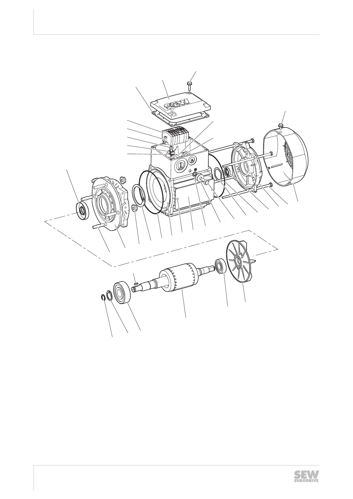
3.2 Basic design of DR2..56 motors
[131]
[132]
[106]
[3]
[22]
[123]
[115]
[113]
[117]
[116]
[118]
[230]
[216]
[103]
[7]
[100]
[12]
[392]
[16]
[109]
[108]
[2]
[10]
[11]
[1]
[44]
[36]
[1451]
[1449]
[41]
[1480]
[30]
[42]
[13]
[35]
[1450]
26857323531
[1] Rotor [22] Hex head screw [106] Oil seal [131] Gasket for cover
[2] Retaining ring [30] Oil seal [108] Nameplate [132] Terminal box cover
[3] Key [35] Fan guard [109] Grooved pin [216] Hex nut
[7] Flanged endshield [36] Fan [113] Cylinder head screw [230] Hex nut
[10] Retaining ring [41] Equalizing ring [115] Terminal board [1449] Hex head screw
[11] Deep groove ball bear-
ing
[42] B-side endshield [116] Terminal clip [1450] Washer
[12] Retaining ring [44] Deep groove ball bear-
ing
[117] Flat head screw [1451] Serrated lock washer
[13] Cap screw [100] Hex nut [118] Washer [1480] O-ring
[16] Stator [103] Stud [123] Hex head screw
25851535/EN – 02/2019
 Loading...