Do you have a question about the sewerin EX-TEC SR5 and is the answer not in the manual?
Details uses for gas detection, interior installations, workplace monitoring, and location.
Details uses for workplace monitoring, location, and gasing/inertisation.
Details uses for location and gasing/inertisation.
Details uses for gas detection and location.
Covers explosion-proof classification and test institute for SR5, SR4, SR2.
Covers functional safety testing in Workplace Monitoring for SR5 and SR4.
Describes Carpet probe for stable surfaces and no extraneous emissions.
Describes Bell probe for unstable surfaces and Search probe for probe holes.
Describes Floating probe for pits and Divisible handprobe for pipes.
Describes Flexible hand probes for house service lines.
Procedure for powering on the detector using the on/off or WPM button.
Explains how to adjust LCD illumination and display contrast.
Details the waiting period for zero point stabilization in fresh air.
Covers switching the pump on/off and adjusting pump power levels.
Details how to manage the alarm signal and buzzer volume.
Explains how to set alarm threshold values using the relevant button.
Explains analogue/digital displays and automatic range switching.
Procedure for manually setting the zero point when automatic fails.
Describes the WPM function for SR5 and SR4, monitoring LEL proximity.
Indicates remaining operation time and low battery warnings.
Safe procedure for powering down the detector.
Details the HS charging adapter and its power connection options.
Explains spontaneous discharge and how to avoid NiCd memory effect.
Covers the frequency and methods for sensitivity testing with gas.
Lists essential items to check during periodic inspections.
Specifies authorized personnel and documentation for servicing.
Details the SPE 1 test set and its applications for pump power, zero point, and sensitivity.
Details the SPE 3 test set and its applications for pump power, zero point, and sensitivity.
Provides a table of test gases for EX-TEC SR5, SR4, SR2, VARIOTEC 8.
Specifies acceptable display readings for methane test gas concentrations.
Specifies acceptable display readings for propane test gas concentrations.
Steps for connecting the detector to a test set and entering adjustment mode.
Shows software version and automatic zero point establishment.
Procedure for calibrating the 10 ppm measuring range.
Procedure for calibrating the 100 ppm measuring range.
Procedure for calibrating the 1,000 ppm measuring range.
Procedure for calibrating the 1.00 vol.% measuring range.
Procedure for calibrating the 0 %LEL range using fresh air.
Procedure for calibrating the 50 %LEL or 59 %LEL ranges.
Procedure for calibrating the 0 vol.% range using fresh air.
Procedure for calibrating the 100 vol.% measuring range.
Steps to configure the detector for local natural gas detection.
How to select the display language for the %LEL range.
How to select the display language for the vol.% range.
Procedure for setting amplification ratios for 10 PPM sensitivity.
Method to verify all LCD display elements are functioning correctly.
Steps to return to normal operating modes from adjustment mode.
Explains the flashing maximum pointer for concentration comparison.
Interpreting heavy gas readings and using CO2 filters.
Safety limits for oxygen concentration to ensure electrical safety.
Procedure for monitoring gas concentration increases or decreases.
Guidelines for cleaning the detector using only a damp cloth.
Recommendations to prevent electrostatic charging of the device.
Instructions for cleaning and replacing fine dust filters.
Details factors affecting sensor sensitivity and methods for regeneration.
Lists the specific EX-TEC and VARIOTEC models included.
Identifies sensor types for PPM, %LEL, and %VOL measurement ranges.
Specifies the detailed measuring ranges and their step increments.
Defines the variable and fixed alarm threshold values.
Provides physical dimensions (W x H x D) and weight.
States the maximum operating duration on a full battery charge.
Lists HS charging adapters, power packs, and vehicle adapters.
Lists various probe systems for different applications.
Lists SPE 1, SPE 2, and SPE 3 test sets for calibration.
Details adjustment errors in PPM range and their remedies.
Details adjustment errors in %VOL range and their remedies.
Indicates component errors requiring SEWERIN Service.
Indicates synchronization alarm or gas sample errors with remedies.
Indicates component errors requiring SEWERIN Service.
Indicates sensor breakage in the thermal combustion sensor.
Indicates sensor breakage in the thermal conductivity sensor.
Indicates sensor breakage in the semiconductor sensor.
Indicates low pump power and suggests troubleshooting steps.
Certifies the PTB 96 ATEX 2166 number for the device.
Lists the ATEX classification: II 2 G EEx ib d IIB T4.
Covers equipment description, test reports, and special conditions.
Warns that battery change/charge must occur outside hazardous areas.
Details modifications to the sensor chamber, including sintered metal elements.
Covers use of data output/alarm for safety-related measures.
Declares compliance with relevant norms and directives for the SR5.
Lists specific EMC and Ex standards the product adheres to.
Confirms adherence to norms and directives for the SR4 model.
States compliance with EU directives such as EMC and ATEX.
Identifies the product as SR 2.
Confirms compliance with electromagnetic compatibility and ATEX directives.
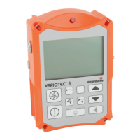
Designates the device as Variotec 8, a gas measuring device.
Lists applicable norms (EMC) and directives for the VARIOTEC 8.
Checks device status, fine-dust filters, and remaining operating hours.
Tests pump low pressure and volume flow rate.
Calibration steps for zero point, fresh air reading, and PPM concentrations.
Calibration steps for zero point and %LEL concentrations.
Calibration steps for zero point and VOL.% concentrations.
Section for recording observations like housing condition or repairs.
| Operating Temperature | -20°C to +50°C |
|---|---|
| Gases Detected | Methane, Propane, Hydrogen |
| Sensors | Catalytic |
| Alarms | Visual, Audible, Vibration |
| Display | LCD |
| Battery Life | Up to 12 hours |