Do you have a question about the Sewhacnm SI 580E and is the answer not in the manual?
Describes warning symbols and their meanings for safe operation.
Outlines the copyright ownership and usage restrictions for the manual.
Provides contact information for customer support and technical inquiries.
Lists important safety precautions to be observed during installation and operation.
Highlights the key characteristics and capabilities of the SI 580E weighing indicator.
Details the technical specifications of the SI 580E, including performance, environment, and communication.
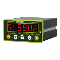
Explains the meaning and operation of each status indicator lamp on the front panel.
Describes the functions and operations associated with each key on the front panel.
Details the usage of hot keys, particularly combinations involving the 'F' key, for special functions.
Provides physical dimensions and required cut-out size for panel mounting.
Lists the accessories and components included with the SI 580E for installation.
Guides the proper connection and installation of load cells to the indicator.
Explains how to enter and navigate the main setup menu for configuring functions.
Details the procedure to enter the setup mode, including password entry if applicable.
Describes the initial steps to begin the calibration process using a test weight.
Guides on setting the maximum weighing capacity and division for the scale.
Explains how to configure the decimal point and the display resolution (digit/division).
Details the procedure for measuring the scale's dead weight for accurate calibration.
Explains how to input the test weight and calculate the span for calibration.
Outlines the initial steps to enter the simulation calibration mode without a test weight.
Guides on setting the maximum capacity of the connected load cell for calibration.
Explains how to set the decimal point and display division value in simulation mode.
Details measuring the scale's dead weight in simulation mode.
Instructs on inputting the load cell's rated output voltage for simulation calibration.
Explains how to access and initiate the F-FUNCTION setting mode for parameter configuration.
Configures the parity bit settings for serial communication.
Sets the baud rate for standard serial communication.
Selects the method for data transmission, e.g., Simplex or Duplex.
Sets the mode for printing data, such as manual or automatic print.
Allows selection of the unit for weight display and printing (kg, g, t).
Defines the layout and content of printed reports.
Configures analog output settings for 4-20mA or 0-10V signals.
Configures parity bits for the extended serial interface.
Sets the baud rate for the extended serial interface.
Selects the data transfer method for the extended serial port.
Defines the range considered as "EMPTY" for zero status indication.
Sets the minimum value for analog output (4mA or 0V).
Sets the maximum value for analog output (20mA or 10V).
Describes how to set a password for the setup mode.
Explains the procedure to modify the existing setup mode password.
Details how to unlock or deactivate the password protection for setup mode.
Allows setting target values for control relay outputs.
Configures free fall values for specific weighing modes.
Guides on performing diagnostic tests for analog values, keys, and digital inputs.
Guides on performing diagnostic tests for relay outputs and serial interfaces.
Details the wiring and connection for RS-422 serial communication.
Explains the connection and wiring for RS-485 serial communication.
Provides instructions for connecting and wiring the RS-232 serial interface.
Describes the first data format for serial transmission, excluding ID number.
Explains the second data format including ID number and transferred data.
Details the third data format, incorporating ID number and status states.
Outlines the specifications for the CAS data format.
Shows the command format and response for reading current weight data.
Details commands and responses for reading internal memory data.
Command to set the scale to zero, equivalent to pressing the ZERO key.
Command to perform the tare function.
Command to activate the hold function, freezing the displayed weight.
Command to initiate a printout of current data.
Provides an example of reading data using commands, illustrating PC to SI580E communication.
Details the electrical specifications for the relay outputs.
Shows the wiring diagram for the relay output terminals.
Lists the technical specifications for the 4-20mA analog output interface.
Guides on how to adjust and calibrate the 4-20mA analog output signal.
Lists the technical specifications for the 0-10V analog output interface.
Guides on how to adjust and calibrate the 0-10V analog output signal.
Explains the available printing formats for serial output.
Details the English language format for printed output.
Lists common errors related to load cell installation and their troubleshooting steps.
States the standard warranty period for the product.
Lists conditions under which the warranty is voided.
Covers additional warranty-related terms and conditions.