GB SGM
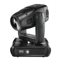
Giotto 1500 User’s Manual 1.02
- 1 -
Table of Contents
S
YMBOLS
U
SED
................................................................................................................. 2
C
HANGES
T
O
T
HIS
M
ANUAL
.................................................................................................... 2
G
ENERAL
W
ARNINGS
........................................................................................................... 3
G
ENERAL
W
ARRANTY
C
ONDITIONS
............................................................................................ 4
1.
I
NTRODUCTION
............................................................................................................................ 6
1.1
M
AIN FEATURES
................................................................................................................................. 6
SPOT
C
ONFIGURATION
................................................................................................................................................7
WASH
C
ONFIGURATION
...............................................................................................................................................9
PROFILE
CONFIGURATION
.........................................................................................................................................11
DIGITAL
CONFIGURATION
...........................................................................................................................................15
1.2
A
CCESSORIES
.................................................................................................................................. 17
1.3
E
LECTRICAL
S
PECIFICATIONS
............................................................................................................... 18
1.4
M
ECHANICAL FEATURES
...................................................................................................................... 19
2.
I
NSTALLATION
............................................................................................................................20
2.1
E
QUIPMENT
..................................................................................................................................... 20
2.2
P
OWER CABLE CONSTRUCTION
.............................................................................................................. 20
2.3
I
NSTALLING THE FIXTURE ON A SUPPORT STRUCTURE
................................................................................. 21
2.4
P
OSITIONING THE FIXTURE
.................................................................................................................. 21
2.5
F
ITTING CLAMPS
............................................................................................................................... 22
2.6
C
ONSTRUCTION OF THE SIGNAL CABLE
.................................................................................................... 23
C
ABLES CONNECTIONS
.............................................................................................................................................23
2.7
C
ONSTRUCTION OF THE DMX TERMINATION
............................................................................................. 24
2.8
W
IRELESS
DMX ............................................................................................................................... 24
2.9
RDM
(R
EMOTE
D
EVICE
M
ANAGEMENT
).................................................................................................. 25
2.10
RS-232
C
ONNECTION
....................................................................................................................... 26
2.11
E
THERNET
-
ARTNET CONNECTION
.......................................................................................................... 26
2.12
F
IRMWARE UPDATING
........................................................................................................................ 26
2.13
A
CCESS TO INTERNAL COMPONENTS
....................................................................................................... 27
M
ODULE CHANGE
...............................................................................................................................................................28
I
NSTALLING
/
REPLACING THE LAMP
.......................................................................................................................31
L
AMP ALIGNMENT
..................................................................................................................................................... 32
Installing / replacing Gobos .....................................................................................................................................33
SPOT
E
PROFILE
CONFIGURATION
............................................................................................................................33
I
NSTALLING
/
REPLACING
R
EFLECTOR
............................................................................................................................34
I
NSTALLING
/
REPLACING
A
NIMATION WHEEL
..........................................................................................................34
SPOT
CONFIGURATION
...............................................................................................................................................34
I
NSTALLING
/
REPLACING THE COLOR FILTERS
.........................................................................................................35
SPOT
C
ONFIGURATION
..............................................................................................................................................35
WASH
CONFIGURATION
..............................................................................................................................................35
R
EPLACING LENS FRONT
...........................................................................................................................................36
3.
M
ICRO
C
OMPUTER
C
ONTROL
........................................................................................................37
3.1
M
ICROCOMPUTER
“C
ONTROL
”.............................................................................................................. 37
3.2
L
ONGLIFE RECHARGEABLE BUFFER BATTERY
.............................................................................................. 37
3.3
N
AVIGAZIONE ALL
’
INTERNO DEL MENU
.................................................................................................... 37
3.4
S
TRUCTURE OF THE MENU
................................................................................................................... 38
SPOT
CONFIGURATION
...............................................................................................................................................38
WASH
CONFIGURATION
..............................................................................................................................................41
PROFILE
CONFIGURATION
.........................................................................................................................................44
DIGITAL
CONFIGURATION
...........................................................................................................................................47
3.5
M
ENU
D
ESCRIPTION
.......................................................................................................................... 50
DMX SETUP .............................................................................................................................................................50
ARTNET SETUP.......................................................................................................................................................53
PAN-TILT SETUP................................................................................................................................................... 54
OPERATING SETUP ................................................................................................................................................57
DISPLAY SETUP.....................................................................................................................................................59

 Loading...