EasyManua.ls Logo

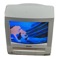
Sharp 13VT-N100 User Manual

Sharp 13VT-N100
90 pages
To Next Page IconTo Next Page
Page #1 background imageLoading...
Page #1 background image
1
13VT-N100
13VT-N150
13VT-CN10
CONTENTS
Page
» IMPORTANT SERVICE SAFETY PRECAUTION............................................................................ 2
» ELECTRICAL SPECIFICATIONS .................................................................................................... 6
» LOCATION OF USER’S CONTROL ................................................................................................ 7
» DISASSEMBLY AND REASSEMBLY .............................................................................................. 9
» INSTALLATION AND SERVICE INSTRUCTIONS......................................................................... 12
» PRECAUTIONS IN REASSEMBLING ........................................................................................... 17
» FUNCTION OF MAJOR MECHANICAL PARTS ........................................................................... 18
» ADJUSTMENT, REPLACEMENT AND ASSEMBLY OF MECHANICAL UNITS ........................... 20
» ADJUSTMENT OF THE VCR ELECTRICAL CIRCUITRY ............................................................ 40
» TROUBLESHOOTING ................................................................................................................... 42
» CHASSIS LAYOUT ........................................................................................................................ 54
» BLOCK DIAGRAM OF TV SECTION ............................................................................................ 56
» BLOCK DIAGRAM OF VCR SECTION ......................................................................................... 58
» OVERALL SCHEMATIC DIAGRAM............................................................................................... 68
» DESCRIPTION OF SCHEMATIC DIAGRAM................................................................................. 70
» PRINTED WIRING BOARD ASSEMBLIES ................................................................................... 82
» REPLACEMENT PARTS LIST ....................................................................................................... 86
» PACKING OF THE SET ............................................................................................................... 103
In the interests of user-safety (Required by safety regulations in some countries ) the set should be restored to its
original condition and only parts identical to those specified should be used.
TV/VCR COMBINATION
Chassis No. B99B
SHARP CORPORATION
MODELS
This document has been published to be used for
after sales service only.
The contents are subject to change without notice.
SERVICE MANUAL
SY9U113VTN100
13VT-N100
13VT-N150
13VT-CN10
Question and Answer IconNeed help?

Do you have a question about the Sharp 13VT-N100 and is the answer not in the manual?

Sharp 13VT-N100 Specifications

General IconGeneral
BrandSharp
Model13VT-N100
CategoryTV VCR Combo
LanguageEnglish

Summary

Service Safety Precautions

General Warnings and Hazards

General warnings about circuit modification, shock hazards, and grounding systems.

X-Radiation and High Voltage Limits

Guidelines for handling high voltage and preventing X-radiation exposure.

Pre-return Safety Checks

Checks for fire and shock hazards before returning the unit to the customer.

Safety-Related Parts

Identifies parts with special safety characteristics and the importance of using identical replacements.

Electrical Specifications

User Control Locations

Front and Rear Panel Controls

Describes controls on the front and rear of the unit.

Remote Control Functions

Explains the buttons and functions of the remote control.

Remote Control Battery Installation

Instructions for inserting batteries into the remote.

Disassembly and Reassembly

Installation and Service Instructions

Circuit Protection (Fuse)

Details the receiver's fuse protection.

X-Radiation Protector Circuit Test

Procedure to test the X-radiation protector.

High Voltage Check Procedure

Steps to verify the high voltage output.

Service Mode and Adjustments

Entering and Exiting Service Mode

Instructions for accessing and leaving the service menu.

Service Adjustment Selection

Method for selecting adjustment items and data.

VCR Service Adjustments

VCO and RF AGC Adjustments

Covers adjustments for VCO and RF AGC circuits.

Screen and White Balance Adjustments

Instructions for screen settings and white balance calibration.

Picture, Tint, Color, Brightness Adjustments

Details on adjusting core picture parameters.

Vertical, Horizontal, Caption Adjustments

Guides for adjusting vertical size, horizontal position, and caption display.

Reassembly Precautions

Mounting the Cassette Controller

Steps for correctly installing the cassette controller unit.

Coupling Mechanism to PWB

Procedure for connecting the mechanism to the main Printed Wiring Board.

Mechanical Parts Function (Top View)

Mechanical Parts Function (Bottom View)

Mechanical Units Adjustment and Assembly

Mechanism Confirmation Adjustment Jigs

Lists required special jigs for precise mechanism adjustments.

Maintenance Checks and Execution Time

Cassette Housing Removal and Installation

Cassette Housing Removal Procedure

Detailed steps for disassembling the cassette housing.

Cassette Housing Reassembly

Instructions for correctly putting the cassette housing back together.

Tape Run Test Without Housing

Method to test tape operation without the cassette housing.

Reel Disk Replacement and Height Check

Reel Disk Removal

Steps to remove the reel disks from the mechanism.

Reel Disk Reassembly and Height Adjustment

Procedures for reassembling and adjusting reel disk height.

Torque Adjustments

Take-Up Torque (FF, REW, Record/Playback)

Procedures for measuring and adjusting take-up torque in various modes.

Video Search Rewind Torque

Steps to check and adjust torque for video search rewind mode.

Tape Tension and Pressure Checks

Video Search Rewind Back Tension

Procedure to check back tension during video search rewind.

Pinch Roller Pressure Check

Method to measure and ensure correct pinch roller pressure.

Tension Pole Position Check

Steps to verify and adjust the tension pole's position.

Record/Playback Back Tension

Tension Pole Position Adjustment

Detailed steps for adjusting the tension pole position.

Record/Playback Back Tension Check

Procedure to check back tension during record and playback modes.

Brake Torque Checks

Brake Torque Check (Supply Side)

Procedure for checking brake torque on the supply reel side.

Brake Torque Check (Take-up Side)

Procedure for checking brake torque on the take-up reel side.

A/C Head Replacement

A/C Head Removal Procedure

Steps for safely removing the A/C head assembly.

A/C Head Replacement and Adjustment

Instructions for installing a new A/C head and initial adjustments.

A/C Head and Reverse Guide Adjustments

A/C Head Height Rough Adjustment

Procedure for initial rough adjustment of the A/C head height.

Reverse Guide Height Adjustment

Steps to adjust the height of the reverse guide for proper tape path.

Tape Drive Train Adjustment

Tape Run Rough Adjustment

Initial steps to ensure smooth tape movement.

A/C Head Height and Azimuth Adjustment

Detailed procedures for fine-tuning A/C head alignment.

Advanced Tape Drive and Head Adjustments

Detailed Tape Run Adjustment

Fine-tuning tape path based on envelope waveform.

A/C Head X Value Adjustment

Procedure for adjusting the A/C head's X value for optimal performance.

Motor Replacements

Capstan D.D. Motor Replacement

Steps for replacing the capstan direct drive motor.

Drum D.D. Motor Replacement

Instructions for replacing the drum direct drive motor.

Drum Assembly and Phase Matching

Upper and Lower Drum Assembly Replacement

Procedures for replacing the drum assembly.

Phase Matching Mechanism Assembly

Steps for assembling phase matching components.

Pinch Drive Cam and Roller Assembly

Method for assembling pinch drive cam and roller.

Shifter Installation

Master Cam and Loading Motor

Master Cam Installation

Steps for installing the master cam onto the mechanism chassis.

Loading Motor Replacement

Instructions for replacing the loading motor.

Cassette Housing Assembly

VCR Electrical Circuit Adjustments

Servo Circuit Adjustment

General overview of servo circuit adjustments.

Head Switching Point Adjustment

Procedure for adjusting the head switching point.

Still Picture Vertical Sync Adjustment

VCR Section Troubleshooting

Power and Electrical Troubleshooting

Guides for diagnosing power supply and general electrical issues.

Cassette Control and Key-in Troubleshooting

Troubleshooting for cassette loading and key input problems.

VCR Component Troubleshooting

Loading Motor and Eject Troubleshooting

Diagnosing issues with the loading motor and tape ejection.

System and Capstan Motor Troubleshooting

Troubleshooting system control and capstan motor failures.

VCR Mechanical Troubleshooting

Reel Pulse and Head Switching Troubleshooting

Diagnosing issues with reel sensors and head switching pulses.

Drum Motor Troubleshooting

Guides for diagnosing drum motor operational problems.

Drum Servo Troubleshooting

Capstan Servo Troubleshooting

Recording and Signal Troubleshooting

E-E Mode Signal Troubleshooting

Diagnosing issues related to the E-E mode signal.

Recording Mode (Luminance) Troubleshooting

Troubleshooting problems with recording luminance.

Playback Mode Troubleshooting

Sound Troubleshooting

Sound E-E Mode Troubleshooting

Diagnosing issues with sound in E-E mode.

Sound Recording Mode Troubleshooting

Troubleshooting sound issues during recording.

Sound Playback Troubleshooting

TV Section Troubleshooting

No Raster Troubleshooting

Guides for diagnosing the absence of a picture on the screen.

Set Not Operating Troubleshooting

Steps to diagnose when the unit is completely unresponsive.

TV Picture and Sound Issues

No Picture, No Sound Troubleshooting

Diagnosing scenarios with both video and audio absent.

No Vertical Scan Troubleshooting

Guides for diagnosing vertical scanning problems.

TV Signal and Remote Troubleshooting

No Sound and No Playback Troubleshooting

Diagnosing issues with sound and playback functionality.

Infrared Remote Control Troubleshooting

Guides for diagnosing remote control operation failures.

Chassis Layout

TV Section Block Diagram

VCR Section Block Diagram

Overall VCR Block Diagram

A comprehensive overview of the VCR system's components.

VCR Servo Process Block Diagram

VCR Control and Safety Diagrams

System Control Block Diagram

Diagram showing the system control circuitry.

Safety Device Block Diagram

Diagram illustrating the safety mechanisms.

VCR Video Signal Flow

VCR Audio Block Diagram

Overall Schematic Diagram

Schematic Diagram Descriptions

Schematic Diagram Notes and Conditions

General notes and voltage/waveform measurement conditions.

Waveforms Description

Illustrations and descriptions of various signal waveforms.

Main-1 Unit Schematic (TV Section)

Main-2 Unit Schematic (TV Section)

Front AV and Power Unit Schematic (TV Section)

Main-3 Unit Schematic (VCR Section)

Main-4 Unit Schematic (VCR Section)

Printed Wiring Board Layouts

CRT and Front AV Unit PWBs

Wiring diagrams for CRT and Front AV units.

Power Unit PWB Layout

Wiring diagram for the Power unit's printed circuit board.

Parts List and Ordering

Replacement Parts Information

Safety notes on replacement parts and ordering procedures.

Picture Tube Parts List

Specific part numbers and descriptions for picture tubes.

Mechanism Chassis Parts

Cassette Housing Control Parts

Cabinet and Mechanical Parts

Supplied Accessories and Packing Parts

Supplied Accessories List

List of items included with the product.

Packing Parts List

List of materials used for packaging the unit.

Packing of the Set

Related product manuals