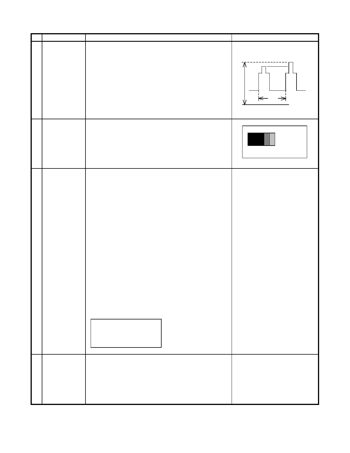
CRT CUTOFF 1. Switch TV to VIDEO mode, BLUE BACK OFF, with
ADJUSTMENT NO VIDEO signal.
(I2C BUS 2. Press R/C to set Picture Normal condition.
CONTROL) 3. Connect the oscilloscope to Red OUT from IC801.
(TP47R)
Range : 1 V/Div (DC)
Sweep : 5 msec/Div
4. Adjust SCREEN VR, so that the tip of signal reach
3.0 Vdc + 0.1 Vdc.
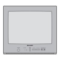
SUB-BRIGHT- 1. Call "SUB-BRI" in service mode. (Receive Cross-
NESS hatch pattern with 5 black level windows)
ADJUSTMENT 2. Adjust the "SUB BRIGHT" bus data in order that
(I2C BUS the line 1, 2 and 3 have the same darkness
CONTROL) wherelse line 4 is slightly brighter than line 1, 2 1 2 3 4 5
and 3 and finally line 5 will be the brighter than
line 4. 1, 2, 3 are in same black level.
WHITE BAL- 1. Receive the "Monoscope Pattern" signal.
# 15,000
K
X: 0.262
ANCE SERVICE 2. Press R/C to set Picture NORMAL condition. Y: 0.272
MODE ADJ. 3. Connect the DC milliammeter between the TP602
(I2C BUS (-) TP603 (+). (MINOLTA COLOR ANALYZER
CONTROL)
4. Check Beam current should be around (990
A)
CA-100)
5. Set it to service mode and adjust the DRI-G-MH, *NOTE: Above DATA can be UP/
& DRI-B-MH data to have a color temperature DOWN by volume key.
of 15,000
K (white).
6. Receive "WHITE" pattern, WITH BURST signal, LOW HIGH
and set BRIGHTNESS Y by generator, to ** 10
cd/m
(MINOLTA CA-100) by reducing LUMINATE
Y signal.
*15,000
K
7. Adjust "CUT-R" & "CUT-G" to get 15,000
K. Then
DRI-GW="DRI-GS"DATA-5
go back NORMAL mode (HIGH BRIGHT**) to DRI-BW=:DRI-BS"DATA-5
check color temperature. If out of range, back
to (1).
Note: This adjustment must be done after
warming up the unit for 30 minutes or
longer with a beam current over 500mA.
DRI-R-MH=32 (FIXED)
DRI-G-MH=33 (FIXED)
DRI-B-MH=37 (FIXED)
DRI-R-MH=32 (FIXED)
Maximum 1. Receive the "Monoscope Pattern" signal.
beam check 2. Press R/C to set Picture NORMAL condition.
3. Connect the DC milliammeter between TP603 (+)
and TP602 (-).
(Full Scale: 3 mA Range)
4. Beam current must be within 990 50
A.
115cd/m21.8cd/m2
1
2
3
CRT CUT-OFF, BACKGROUND AND SUB-CONTRAST ADJUSTMENT
4
Adjusting procedure/conditions
1 V
3.0 Vdc
0
12