RF AGC Adjustment
1. Receive a good local channel.
2. Enter the service mode signal category and select
the service adjustment "AGC".
3. Set the data value to point where no noise or beat
appears.
4. Select another channel to confirm that no noise or
beat appears.
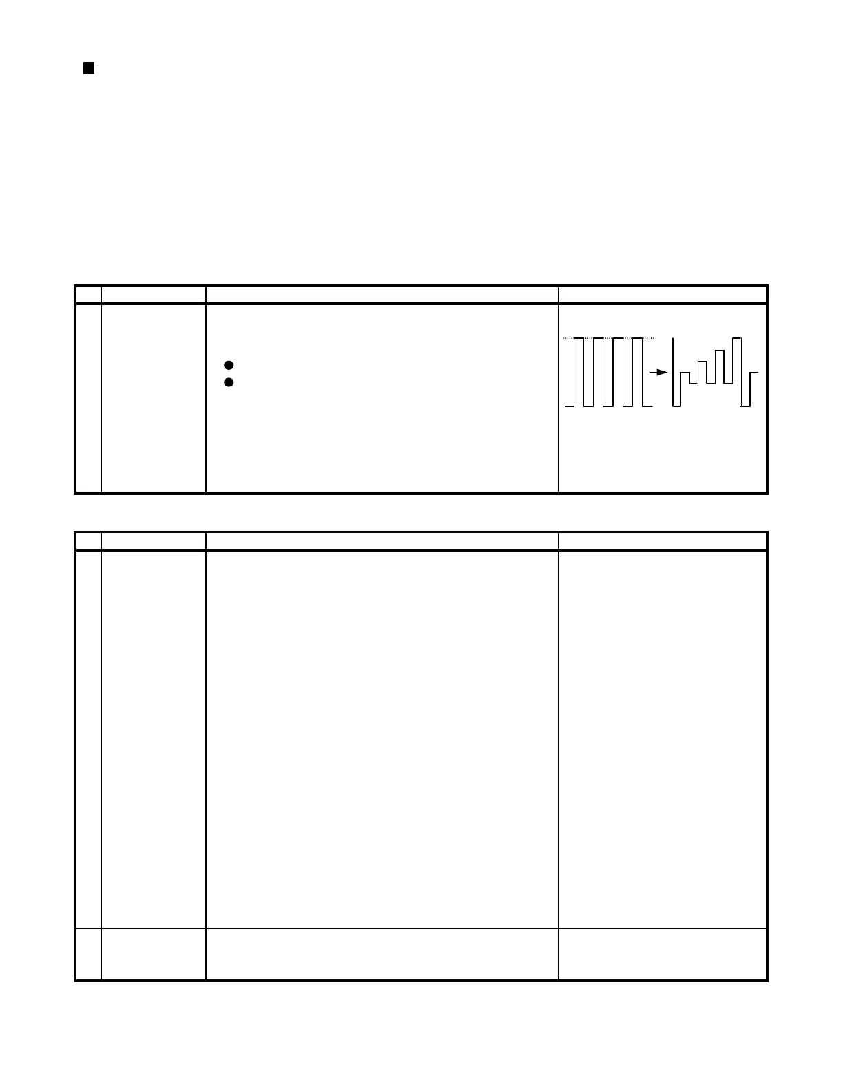
SUB-TINT (I
C
1. Receive the "Color Bar" signal through AV in. WAVEFORM 1
BUS CONTROL) 2. Connect the oscilloscope to TP47B (Pin (5) of SAME LEVEL
P882) BLUE-OUT.
Range : 10 V/div. (AC) (Use probe 10:1)
Sweep time : 10
sec/div.
3. Call the "SUB-TINT" mode in service mode. Adjust
the "SUB-TINT" bus data to obtain the waveform W Y CY G MG R B
shown as Fig 1.
4. "SUB-TINT" bus data decrease 4 steps to get final Fig 1 Fig 2
waveform. (Fig 2.)
5. Clear the SERVICE mode.
V-SLOPE (I
C
1. Receive the Monoscope Pattern Signal.
BUS CONTROL) 2. Call the "V-LIN" mode.
3. Increase or decrease "V-LIN" by Volume key till
the horizontal line in the center of monoscope is
just at the position where the blanking starts.
V-CENTER (I
C
1. Call the "V-CENT" mode.
BUS CONTROL) 2. Increase or decrease "V-CENT by Volume key till
the picture is centered.
V-AMP (I
C
1. Call the "V-AMP" mode.
BUS CONTROL) 2. Increase or decrease "V-AMP" by Volume key to
set overscan to 10.0% typical.
Adjustment Spec 10.0% range 1%
S-CORRECTION
(I
C BUS CON-
TROL)
H-CENTER 1. Call the "H-CENT" mode.
2. Increase or decrease "H-CENT" by Volume key
to center the picture horizontal.
Focus 1. Receive the "Monoscope Pattern" signal.
Adjustment 2. Press the R/C to set Picture NORMAL condition.
3. Adjust the focus control to get the best focus.
HORIZONTAL AND VERTICAL DEFLECTION LOOP ADJUSTMENT
Adjusting procedure/conditions
1
14V-L70M
Adjusting procedure/conditions
1
2
3
4
5
6
FIXED DATA, NO NEED TO ADJUST.
11