21F-PD250 / 21F-PT220 / 21F-PA18 / 21F-PA18(B)
3 – 21
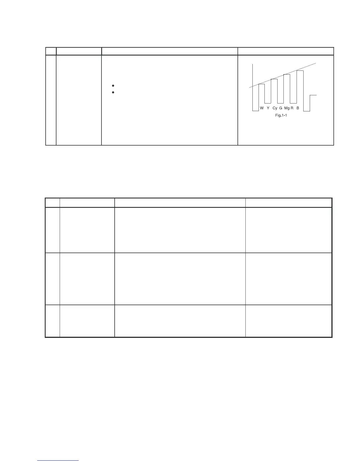
8. NTSC CHROMA ADJUSTMENT
No.
Adjustment point
Adjustment procedure/conditions Waveform and others
SUB-TINT
(I
2
CBUS
CONTROL)
1
1) Receive the "NTSC 3.58 Color Bar" signal thru
AV in.
2) Connect the oscilloscope to B-Amp Transistor
Base (JUMPER 410).
Range : 100mV/Div.(AC)(Use Probe 10:1)
Sweep time : 10 µsec/Div.
3) In Service mode, go to V07,pressR/C Y-mute
(Hex F4) or FLASHBACK Key.
4) Call the "V07" data in service mode. Adjust the
"V07" bus data to obtain the waveform shown as
Fig. 1-1.
5) Disable Y-Mute by pressing key (Hex E4) or
FLASHBACK, then clear the SERVICE mode.
9. PROTECTOR OPERATION CHECKING
No.
Adjustment point
Adjustment procedure/conditions Waveform and others
BEAM 1) Receive "Monoscope Pattern" signal.
2) Set CONTRAST MAX.
3) Set BRIGHT MAX.
4) During the Collector & Emitter of Q853/4/5 short,
make sure the protector ON and switch to standby
mode.
1 * Select one of Q853/4/5 to do
each short.
H, V PROTECTOR 1) Receive "Monoscope Pattern" signal.
2) Connect output of Bias Box to D602 cathode
(C602 positive).
3) Set voltage of Bias Box to 18V and make sure
the protector is not working.
4) Set voltage of Bias Box to 27V , and make sure
the protector is working.
2
OTHER
PROTECTOR
1) Once finish rectified Electrolytic Capacitor short
testing in +B line, check all possible damaged
components on +B line.
(Use random selected set for inspection)
3
PROTECTOR