EasyManua.ls Logo

Sharp 27J-S100 User Manual

Sharp 27J-S100
47 pages
To Next Page IconTo Next Page
Page #1 background imageLoading...
Page #1 background image
- 1 -
27J-S100/180/260
CJ27S10/26
SERVICE MANUAL
In the interests of user-safety (Required by safety regulations in some countries ) the set should be restored to its
original condition and only parts identical to those specified should be used.
COLOR TELEVISION
Chassis No. SN-71
Specifications are subject to change without prior
notice.
POWER INPUT............................................... 120 V AC 60 Hz
POWER RATING ............................................................ 126 W
PICTURE SIZE ...................................... 2,193cm2(340sq inch)
CONVERGENCE ........................................................ Magnetic
SWEEP DEFLECTION ............................................... Magnetic
FOCUS .......................................... Hi-Bi-Potential Electrostatic
INTERMEDIATE FREQUENCIES
Picture IF Carrier Frequency ................................ 45.75 MHz
Sound IF Carrier Frequency................................. 41.25 MHz
Color Sub-Carrier Frequency ............................... 42.17 MHz
.............................................................................. (Nominal)
AUDIO POWER .........................................................................
OUTPUT RATING ........................... 2.6W (at 10% distortion)
SPEAKER
SIZE ................................................................... 8cm(Round)
VOICE COIL IMPEDANCE .......................... 8ohm at 400 Hz
ANTENNA INPUT IMPEDANCE
VHF/UHF................................................75 ohm Unbalanced
TUNING RANGES
VHF-Channels ........................................................... 2thru 13
UHF-Channels ........................................................ 14thru 69
CATV Channels .......................................................1thru 125
............................................................... (EIA, Channel Plan)
ELECTRICAL SPECIFICATIONS
CONTENTS
Page
» ELECTRICAL SPECIFICATIONS ............................................................................................. 1
» IMPORTANT SERVICE SAFETY PRECAUTION ..................................................................... 2
» LOCATION OF USER'S CONTROL.......................................................................................... 6
» INSTALLATION AND SERVICE INSTRUCTIONS .................................................................... 9
» CHASSIS LAYOUT .................................................................................................................16
» BLOCK DIAGRAM ..................................................................................................................18
» PRINTED WIRING BOARD ASSEMBLIES............................................................................. 20
» SCHEMATIC DIAGRAMS ....................................................................................................... 26
» REPLACEMENT PARTS LIST ................................................................................................ 42
» PACKING OF THE SET .......................................................................................................... 60
MODELS
27J-S100/180/260
CJ27S10/26
27J-S180
27J-S100/S260
CJ27S10/26
SHARP ELECTRONICS CORPORATION
Service Headquarters: Sharp Plaza, Mahwah, New Jersey 07430-2135
SHARP ELECTRONICS OF CANADA LTD.
335 Britannia Road East Mississauga,Ontario L4Z 1W9 Canada
,,,,,,,,,
,,,,,,,,,
,,,,,,,,,
,,,,,,,,,
,,,,,,,,,
,,,,,,,,,
,,,,,,,,,
,,,,,,,,,
S37W727J-S100
Question and Answer IconNeed help?

Do you have a question about the Sharp 27J-S100 and is the answer not in the manual?

Sharp 27J-S100 Specifications

General IconGeneral
BrandSharp
Model27J-S100
CategoryTV
LanguageEnglish

Summary

Electrical Specifications

Important Service Safety Precautions

X-Radiation and High Voltage Limits

Limits and precautions related to X-radiation and high voltage.

Important Service Safety Precautions (Continued)

Before Returning the Receiver (Fire & Shock Hazard)

Safety checks to perform before returning the receiver to the user.

Safety Notice

Warnings regarding the use of correct replacement parts for safety.

Location of User's Control

Location of Controls

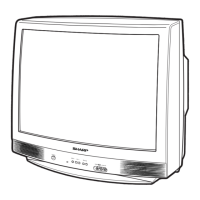
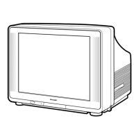
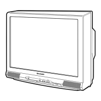
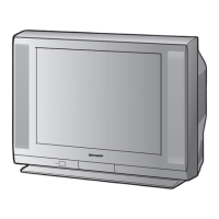
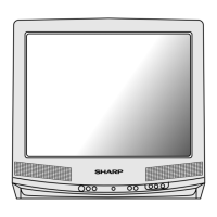
Identifies the location of various controls on the TV unit.

Basic Remote Control Functions

Explains the functions of the remote control buttons.

Installation and Service Instructions

Circuit Protection

Details on the receiver's circuit protection fuse.

X-Radiation Protector Circuit Test

Procedure to test the X-radiation protection circuit.

High Voltage Check

Procedure for checking and verifying high voltage levels.

Service Mode Adjustments

Service Mode

Instructions on entering and exiting service mode.

Service Number Selection

How to select specific service adjustment numbers.

Data Number Selection

Method for adjusting data numbers for service settings.

Adjustment Procedures

VCO Adjustment

Procedure for adjusting the Voltage Controlled Oscillator.

RF AGC Adjustment

Procedure for adjusting the Radio Frequency Automatic Gain Control.

Screen Adjustment

Steps for adjusting screen size and linearity.

White Balance Adjustment

Procedure for adjusting white balance for accurate colors.

Sub-Picture Adjustment

Steps for adjusting sub-picture settings.

Sub-Tint Adjustment

Procedure for adjusting the tint control.

Sub-Color Adjustment

Procedure for adjusting color levels.

Further Adjustment Procedures

Sub-Brightness Adjustment

Procedure for adjusting the brightness control.

Vertical-Size and Linearity Adjustment

Adjusting vertical size and linearity.

Vertical Phase Adjustment

Procedure for adjusting vertical phase.

Horizontal Position Adjustment

Procedure for centering the horizontal picture position.

Caption Position Adjustment (Horizontal)

Adjusting the horizontal position of on-screen captions.

3.58MHz Trap Adjustment

Procedure for adjusting the 3.58MHz trap.

Sharpness and Audio Balance Adjustments

Adjusting sharpness and audio balance.

MTS Adjustment

MTS Level Adjustment

Procedure for adjusting MTS audio level.

Stereo VCO Adjustment

Procedure for adjusting stereo VCO.

Filter Adjustment

Procedure for filter adjustment.

Separation Adjustment

Procedure for adjusting audio separation.

P-in-P Adjustment

P-in-P Y Level Adjustment

Adjusting the picture-in-picture level.

P-in-P Tint Adjustment

Adjusting picture-in-picture tint.

P-in-P Color Adjustment

Adjusting picture-in-picture color.

P-in-P Y-Off Set Adjustment

Adjusting picture-in-picture Y-offset.

P-in-P H-Position Adjustment

Adjusting picture-in-picture horizontal position.

P-in-P Burst Gate Pulse (for MAIN)

Adjusting P-in-P burst gate pulse.

Description of Schematic Diagram

Waveform Measurement Conditions

Conditions for measuring waveforms in the schematic.

Waveforms

Visual representation of various signal waveforms.

Chassis Layout

Block Diagram

Printed Wiring Board Assemblies

Schematic Diagram: 27J-S100/CJ27S10 Main1

Schematic Diagram: 27J-S180 Main1

Schematic Diagram: 27J-S260 / CJ27S26 Main1

Schematic Diagram: 27J-S100/CJ27S10 Main2

Schematic Diagram: 27J-S180 Main2

Schematic Diagram: P in P

Schematic Diagram: 27J-S260/CJ27S26 Main2

Schematic Diagram: CRT

Indication of Sensor IC Voltage (IC2001)

Voltage indications for sensor IC2001.

Replacement Parts List

How to Order Replacement Parts

Instructions on how to order replacement parts.

Cabinet Parts

Cabinet Parts Location

Packing of the Set

Related product manuals