11
32U-S50B
32U-S60B
C. C Display Position Adjustment
1. Receive the lion head pattern signal.
2. Select "EX2" to display the text box.
3. Adjust the "EX2" bus data to let the text box displayed
in the center.
Vertical-Size and Linearity Adjustments
1. Receive a good local channel.
2. Enter the service mode and select the service
adjustment "D03" for V-size.
3. Adjust the "D03" bus data to get the proper V-size.
4. For V-linearity adjustment, select data bus "D05" and
adjust to get the proper vertical linearity.
Note: Aging for 10 min before adjustment. After the
adjustment of V-center and V-size, re-
adjustment for this V-line.
Vertical Phase Adjustment
1. Enter the service mode and input "D01" data value
to "00h".
2. Adjust "D18" data value so that picture is centered.
Horizontal Position Adjustment
1. Receive a good local channel.
2. Enter the service mode and select the service
adjustment "D02".
3. Adjust "D02" data value so that picture is centered.
Horizontal-Size Adjustment
1. Receive a good local channel.
2. Enter the service mode and select the service
adjustment "D04" for H-size.
3. Adjust the "D04" bus data to get the proper H-size.
EW-Parabola
1. Receive a good local channel.
2. Enter the service mode and select the service
adjustment "D07" for EW parabola.
3. Adjust the "D07" bus data to get the proper vertical
straight line for both left and right side.
EW-Trapezium
1. Receive a good local channel.
2. Enter the service mode and select the service
adjustment "D08" for EW-Trapezium.
3. Adjust the "D08" bus data to get the best position
display.
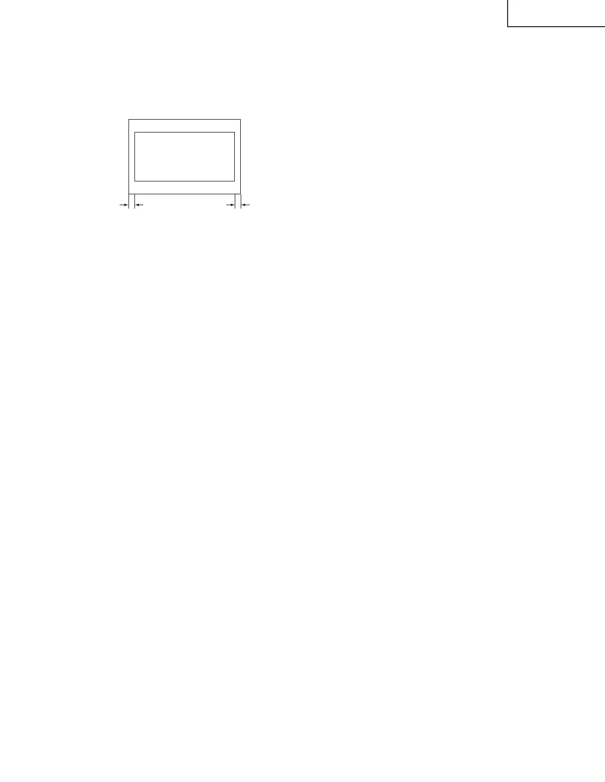
DISPLAY OF TEXT BOX
TEXT BOX
A
B
| A-B | / 2
SPEC INSPECTION:| A-B | / 2
<
=
5mm
Ë
MTS ADJUSTMENT
MTS Level Adjustment
1. Set the sound volume above 1.
Monoral signal: 400Hz, 100% modulation
2. Confirm "EX4" data is "5Ah".
3. Vary the "M01" bus data until the voltage to pin (39)
of IC3001 to become the value as stated below.
SETTING VOLTAGE
ADJ spec : 490±10mVrms
CHK spec: 490±20mVrms
MTS VCO Adjustment
1. Keep the unit in no-signal state.
2. Connect the frequency counter to pin (39) of IC3001.
3. Connect a capacitor (100µF, 50V) in between
positive(+) side of C3005 and ground.
4. Enter the service mode and select the service
adjustment "M02"
5. Adjust the data so that the frequency counter reads
62.94 ±0.75kHz.
Filter Adjustment
1. Feed the following stereo pilot signal to pin (14) of
IC3001 at C3005 open.
Stereo pilot signal: 9.4kHz, 600mVrms.
2. Enter the service mode and select the service
adjustment "M03".
3. Adjust the data until "OK" appears in position on the
screen. Make sure the "OK" is displayed almost at
the center of the data range.
Separation Adjustment
1. Input "SIGNAL 1" and vary the "M04" bus data to get
the minimun AC voltage to pin (39) of IC3001.
2. Input "SIGNAL 2" and vary the "M05" bus data to get
the minimun AC voltage to pin (39) of IC3001.
SIGNAL 1:
300Hz, 30% modulation, Lch only, NR-ON
SIGNAL 2: 3kHz, 30% modulation, Lch only, NR-ON
Note: SIGNAL 1 Adj. for widebando
SIGNAL 2 Adj. for spectral
Check the output of the speaker at the maximum
volume as stated below.
Confirmation spec:
ADJ spec: above 25 dB
CHK spec: above 20 dB