1
sec..
1
sec
0.6
sec.
1
sec.
1
sec.
1
sec.
1
sec.
1
sec.
0.6
sec.
1
sec.
1
sec.
1
sec.
1
sec.
1
sec.
1
sec.
1
sec.
1
sec.
1
sec.
0.6
sec.
0.6
sec.
1
sec.
0.6
sec.
1
sec.
0.6
sec.
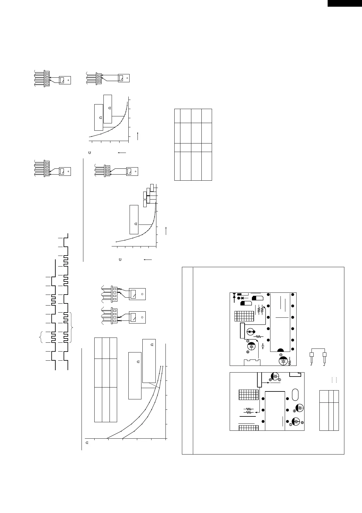
100
80
60
40
20
0
-10 0 10 20 30 40
Resistance
Thermistor
Room temperature
Heat exchange
Color
Yellow
Orange
To measure the resistance, first remove
the soldering as shown at right.
Room temperature
thermistor TH1
Heat exchange
thermistor TH2
Tester Tester
CN4
1 4
1 time
Compressor lock
Overheat of the compressor
2 times
ON
OFF
ON
OFF
Signal
No. 1 to No. 2
No. 3 to No. 4
Figure 1 Temperature properties of indoor thermistors
500K
400K
300K
200K
100K
0
-20 0 20 60 80 100 120
3.06K5.78K
4.17K 2.28K
1.72K
1 4
40K
30K
20K
10K
0
-20 0 20 60
40
1 4
Figure 2 Temperature properties of outdoor thermistors
Connector
CN8
Connector
CN8
AU-X138E
AU-X108E
AU-X138E
AU-X108E
1 6
AE-X138E
AE-X108E
TH2, TH3 heat exchange thermistor
TH1 compressor thermistor
TH2
Connector
CN8
Temperature (°C)
Temperature (°C)
Tester
Tester
Thermistor To measure the
resistance, first
remove the
connector from the
board.
ColorNo. Connector
Compressor
thermistor
Heat exchanger
pipe thermistor
Outdoor temp.
thermistor
TH1
TH2
TH3
No. 1 to 2
No. 3 to 4
White
Orange
No. 5 to 6
Green
Connector
CN8
1 6
AE-X138E
AE-X108E
Microcomputer
terminal
Input
signal
To Outdoor control board
Adaptor
(GND)
(R31)
0 Low input
1 High input
TEST 1)Pin No. 42
TEST 2)Pin No. 43
1
0
K
Heat exchange thermistor
TH2 (orange)
25°C resistance 15 K
Room temperature
thermistor TH1 (yellow)
25°C resistance 10 K
25°C resistance
45 K
Resistance ( )
Resistance ( )
0°C resistance
14.5 K
25°C resistance
4.428 K
1 4
32
33
6
C23
C20
JP10
OSC1
CN
Cool / 40Hz
R31
R32
JP1
JP9
JP11
C17
JP13
JP14
R21
AE-X138E, AU-X138E
11
64
Cool / 40Hz
(QFS-GA015JBE0)
LED1
JP9
JP10
JP11
C44
IC1
C45
C46
D10
JP20
JP8
Q10
E
C
B
Q9
E
C
B
D11
CN10
R32
R31
R30
R33
AE-X108E, AU-X108E
Cautions when attaching or removing the board
When operating only the outdoor unit (cooling 40 Hz fixed mode) To make
only the outdoor unit run in cooling mode, short the places marked with
arrows below with an adaptor, and apply a voltage of 220 ~ 240 V AC to 1
and N on the terminal board.
(Avoid operating the outdoor unit alone for long periods of time.)