EasyManua.ls Logo

Sharp AE-X12PSR User Manual

Sharp AE-X12PSR
73 pages
To Next Page IconTo Next Page
Page #1 background imageLoading...
Page #1 background image
SERVICE MANUAL
AY-X9PSR
SC213AYX9PSR/C
Parts marked with " " are important for maintaining the safety of the set. Be sure to replace these parts with specified ones for maintaining the
safety and performance of the set.
This document has been published to be used for
after sales service only.
The contents are subject to change without notice.
CHAPTER 1. SPECIFICATION
[1] SPECIFICATION ...........................................1-1
[2] EXTERNAL DIMENSION ..............................1-2
[3] WIRING DIAGRM..........................................1-3
[4] ELECTRICAL PARTS....................................1-4
CHAPTER 2. EXPLANATION OF CIRCUIT AND OP-
ERATION
[1] BLOCK DIAGRAMS ......................................2-1
[2] MICROCOMPUTER CONTROL SYSTEM........2-3
[3] FUNCTION..................................................2-18
CHAPTER 3. FUNCTION AND OPERATION OF PRO-
TECTIVE PROCEDURES
[1] PROTECTION DEVICE FUNCTIONS AND
OPERATIONS ...............................................3-1
[2] AIR CONDITIONER OPERATION IN
THERMISTOR ERROR...............
..................3-2
[3] THERMISTOR TEMPERATURE CHAR-
ACTERISTICS...............................................3-3
[4] GENERAL TROUBLESHOOTING CHART....3-6
[5] MALFUNCTION (PARTS) CHECK METH-
OD..................................................................3-8
[6] CHART .........................................................3-10
[7] TROUBLE SHOOTING GUIDE ................... 3-11
CHAPTER 4. REFRIGERATION CYCLE
[1] SCHEMATIC DIAGRAM ................................ 4-1
[2] STANDARD CONDITION ...........................
... 4-1
[3] TEMPERATURE AT EACH PART AND
PRESSURE IN 3-WAY VALVE....................... 4-2
[4] PERFORMANCE CURVES ........................... 4-2
CHAPTER 5. DISASSEMBLY PROCEDURE
[1] INDOOR UNIT ............................................... 5-1
[2]
[3]
OUTDOOR UNIT ........................................... 5-4
CHAPTER 6. OPERATION MANUAL
CONTROL BOX............................................. 5-7
PA
RTS LIST
CONTENTS
SPLIT TYPE ROOM AIR CONDITIONER
INDOOR UNIT OUTDOOR UNIT
MODELS
In the interests of user-safety (Required by safety regulations in some countries) the set should be restored to its original condition and only parts
identical to those specified should be used.
AE-X9PSR
AY-X12PSR AE-X12PSR
AY-X9PSR
MODELS
CHAPTER 7. INSTALLATION MANUAL

Table of Contents

Question and Answer IconNeed help?

Do you have a question about the Sharp AE-X12PSR and is the answer not in the manual?

Sharp AE-X12PSR Specifications

General IconGeneral
RefrigerantR32
Power Supply220-240V, 50Hz
Outdoor Unit Dimensions (W x H x D)720 x 495 x 270 mm
TypeSplit Type
Cooling Capacity12000 BTU/h

Summary

CHAPTER 1. PRODUCT SPECIFICATION

[1] SPECIFICATION

Detailed technical specifications for AY-X9PSR/AY-X12PSR models.

[2] EXTERNAL DIMENSION

Unit Dimensions

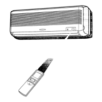
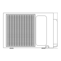
Drawings and measurements for indoor and outdoor units.

[3] WIRING DIAGRAM

Indoor and Outdoor Wiring Diagrams

Wiring diagrams illustrating connections within the indoor and outdoor units.

[4] ELECTRICAL PARTS

Model-Specific Electrical Parts

Lists of electrical components for different AY/AE models.

CHAPTER 2. EXPLANATION OF CIRCUIT AND OPERATION

[1] BLOCK DIAGRAMS

Block diagrams illustrating indoor and outdoor unit systems.

[2] MICROCOMPUTER CONTROL SYSTEM

Indoor Unit Control Circuit

Detailed electronic control circuit diagram for the indoor unit.

PRINTED WIRING BOARDS

Indoor Unit PWB Layout

Layout diagram of the indoor unit's printed wiring board.

OUTDOOR UNIT CONTROL CIRCUITRY

Inverter Module Control Circuit

Electronic control circuit for the outdoor unit inverter module.

POWER SUPPLY BOARD SCHEMATIC

Power Supply Board Circuit Diagram

Schematic diagram of the power supply board components.

INVERTER MODULE BOARD LAYOUT

Inverter Module PWB Layout

Layout diagram of the inverter module's printed wiring board.

POWER SUPPLY BOARD LAYOUT

Power Supply Board PWB Layout

Layout diagram of the power supply board's printed wiring board.

CHAPTER 3. FUNCTION AND OPERATION OF PROTECTIVE PROCEDURES

Functions

Key operational functions and protection mechanisms of the air conditioner.

Compressor Protection and Thermistor Functions

Compressor Protection

Covers compressor protection, thermistor errors, and defrosting.

OPERATIONAL MODES AND PWM CIRCUIT

Modes and Drying Control

Details on auto mode, airflow, drying, and temperature settings.

PWM Circuit Explanation

Explanation of the PWM circuit, including PFC.

CIRCUITRY EXPLANATIONS

PFC Drive Circuit Sequence

Detailed explanation of the PFC drive circuit sequence.

IPM Drive Circuit Explanation

Explanation of the IPM drive circuit and its power supply.

PROTECTIVE DEVICE FUNCTIONS

Protection Device Functions and Operations

Table detailing protection functions, detection, reset, and display.

Thermistor Error Operation

Indoor/Outdoor Thermistor Error Handling

How the unit operates during indoor/outdoor thermistor errors.

THERMISTOR CHARACTERISTICS

Thermistor Temperature Data

Tables showing temperature vs. resistance for thermistors.

GENERAL TROUBLESHOOTING CHART

Indoor Unit Troubleshooting

Common issues and solutions for the indoor unit.

Remote Control & Compressor Troubleshooting

Remote Control and Compressor Issues

Troubleshooting remote control, vane, and compressor problems.

MALFUNCTION DIAGNOSIS METHODS

IPM/Compressor Malfunction Diagnosis

Flowchart for diagnosing IPM and compressor issues.

DC OVER CURRENT ERROR

FAILURE CODE CHARTS

Indoor Unit Failure Codes

Indoor unit error codes, indicator lamps, and digital display.

Outdoor Unit Failure Codes

Outdoor unit error codes, blink times, and fault messages.

TROUBLESHOOTING GUIDE

Display E1/E2 Troubleshooting

Steps to diagnose and resolve E1 or E2 display errors.

Display E6, E3, E7, E8, EA Troubleshooting

Steps to diagnose and resolve E6, E3, E7, E8, EA display errors.

Display EC Troubleshooting

Steps to diagnose and resolve EC display errors.

Display EU, EP, P1 Troubleshooting

Steps to diagnose and resolve EU, EP, P1 display errors.

Display E9, EE, P1 Troubleshooting

Steps to diagnose and resolve E9, EE, P1 display errors.

Display P4, P2, P5, P6 Troubleshooting

Steps to diagnose and resolve P4, P2, P5, P6 display errors.

Display P7, P8, P9 Troubleshooting

Steps to diagnose and resolve P7, P8, P9 display errors.

CHAPTER 4. REFRIGERATION CYCLE

[1] SCHEMATIC DIAGRAM

Schematic diagram of the air conditioner's refrigeration cycle.

PERFORMANCE CURVES

Cooling and Heating Performance Curves

Input vs. output capacity curves for cooling and heating modes.

CHAPTER 5. DISASSEMBLY PROCEDURE

[1] INDOOR UNIT DISASSEMBLY

Step-by-step instructions for disassembling the indoor unit.

OUTDOOR UNIT DISASSEMBLY

[2] OUTDOOR UNIT DISASSEMBLY

Step-by-step instructions for disassembling the outdoor unit.

CONTROL BOX DISASSEMBLY

[3] CONTROL BOX DISASSEMBLY

Instructions for disassembling the control box.

CHAPTER 7. INSTALLATION MANUAL

SAFETY PRECAUTIONS

Essential safety guidelines for installation.

INDOOR UNIT SETUP

Indoor Unit Installation Procedures

Procedures for installing the indoor unit, including piping.

PIPING AND AIR REMOVAL

Refrigerant Pipe Connection and Air Removal

Guidelines for connecting pipes and removing air from the system.

CABLE CONNECTION AND TEST RUN

Cable Connection and Test Run Procedures

Connecting cables and performing a test run.

CHAPTER 6. OPERATION MANUAL

USING THE REMOTE CONTROL

Instructions on using the remote control, including battery loading.

BASIC OPERATION

Basic Operation Guide

Guide to basic operation using the remote control buttons.

AIR FLOW DIRECTION AND FULL POWER

Air Flow Adjustment and Full Power

Adjusting airflow and using the full power operation mode.

TIMER OPERATION

Setting Timer ON and OFF

Instructions for setting TIMER ON and TIMER OFF.

ENERGY SAVING TIPS

Temperature and Power Management

Recommendations for setting temperatures and managing power usage.

Power Failure and Heating Notes

Unit behavior during power failure and notes on heating efficiency.

PARTS GUIDE

[1] INDOOR UNIT PARTS

Diagram and list of indoor unit parts.

AY-X9PSR Indoor Unit Parts List

AY-X9PSR Indoor Unit Parts

Specific part numbers for AY-X9PSR indoor unit components.

AY-X12PSR Indoor Unit Parts List

AY-X12PSR Indoor Unit Parts

Specific part numbers for AY-X12PSR indoor unit components.

ACCESSORY AND INDOOR UNIT PARTS

[2] ACCESSORY PARTS

List of included accessories like remote control and manuals.

[3] INDOOR UNIT PARTS DIAGRAM

Diagram and list of indoor unit components.

[4] OUTDOOR UNIT PARTS

Outdoor Unit Parts Diagram

Diagram of outdoor unit components.

AE-X9PSR Outdoor Unit Parts List

AE-X9PSR Outdoor Unit Parts

Specific part numbers for AE-X9PSR outdoor unit components.

AE-X12PSR Outdoor Unit Parts List

AE-X12PSR Outdoor Unit Parts

Specific part numbers for AE-X12PSR outdoor unit components.

[5] OUTDOOR PACKING PARTS

Outdoor Unit Packing Components

List of packing materials for outdoor units.

Related product manuals