EasyManua.ls Logo

Sharp AF-S125FX User Manual

Sharp AF-S125FX
32 pages
To Next Page IconTo Next Page
Page #1 background imageLoading...
Page #1 background image
PREFACE
SAFETY PRECAUTIONS ...................................i
INSULATION RESISTANCE TEST.....................i
CHAPTER 1. PRODUCT SPECIFICATION
[1] SPECIFICATION............................................ 1-1
[2] WIRING DIAGRAM...................................... 1-10
[3] EXTERNAL DIMENSION............................. 1-10
CHAPTER 2. MICROCOMPUTER CONTROL SYS-
TEM
[1] ELECTRONIC CONTROL CIRCUIT DIA-
GRAM ............................................................ 2-1
[2] PRINTED WIRING BOARD ........................... 2-2
CHAPTER 3. TROUBLESHOOTING GUIDE
[1] REFRIGERATION CYCLE DIAGRAM...........3-1
[2] TROUBLESHOOTING GUIDE......................3-1
REPLACEMENT PARTS LIST
SERVICE MANUAL
AFS120FX
SHARP CORPORATION
CONTENTS
Parts marked with " " are important for maintaining the safety of the set. Be sure to replace these parts with specified ones for
maintaining the safety and performance of the set.
This document has been published to be used
for after sales service only.
The contents are subject to change without notice.
Room Air Conditioner
AF-S60FX
AF-R80FX
AF-S80FX
AF-S85FX
AF-R100FX
AF-S100FX
AF-R120FX
AF-S120FX
AF-S125FX
MODELS
In the interests of user-safety (Required by safety regulations in some countries) the set should
be restored to its original condition and only parts identical to those specified should be used.
Question and Answer IconNeed help?

Do you have a question about the Sharp AF-S125FX and is the answer not in the manual?

Sharp AF-S125FX Specifications

General IconGeneral
BrandSharp
ModelAF-S125FX
CategoryAir Conditioner
LanguageEnglish

Summary

Preface

Safety Precautions

Essential safety guidelines for servicing the air conditioner unit.

Insulation Resistance Test

Procedure for testing insulation resistance to prevent electric shock hazards.

Chapter 1. Product Specification

Specification

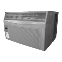
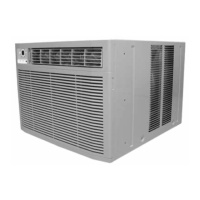
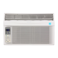
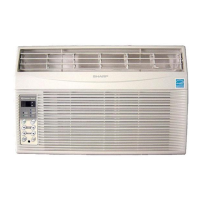
Detailed specifications for various air conditioner models, including capacity, electrical data, and dimensions.

Wiring Diagram

Electrical wiring diagram illustrating component connections for the unit.

External Dimension

Diagrams and measurements of the unit's external dimensions.

Chapter 2. Microcomputer Control System

Electronic Control Circuit Diagram

Detailed circuit diagram for the microcomputer control system.

Printed Wiring Board

Layouts for the main and display control printed wiring boards.

Chapter 3. Troubleshooting Guide

Refrigeration Cycle Diagram

Diagram explaining the room air conditioner's refrigeration cycle and refrigerant flow.

Troubleshooting Guide

Classification of common troubles, voltage limits, and general troubleshooting steps.

Replacement Parts List

Chassis and Lower Shutter Frame (Small)

List of chassis and lower shutter frame parts for small models.

Electric Control System, Cabinet, Shutter, and Front Panel (Small)

Parts for electric control, cabinet, shutter, and front panel for small models.

Airflow and Refrigerant System (Small)

List of airflow and refrigerant system components for small models.

Accessories (Small)

List of accessory parts for small models.

Others (Small)

Miscellaneous parts for small models.

Chassis and Lower Shutter Frame (Medium)

List of chassis and lower shutter frame parts for medium models.

Electric Control System, Cabinet, Shutter, and Front Panel (Medium)

Parts for electric control, cabinet, shutter, and front panel for medium models.

Airflow and Refrigerant System (Medium)

List of airflow and refrigerant system components for medium models.

Accessories (Medium)

List of accessory parts for medium models.

Others (Medium)

Miscellaneous parts for medium models.

Related product manuals