Do you have a question about the Sharp CD-C471H and is the answer not in the manual?
General safety warnings and precautions for servicing the unit, especially regarding laser safety.
Specific service notes and mandatory tests required for units sold in the UK.
Detailed technical specifications for the CD stereo system's various components.
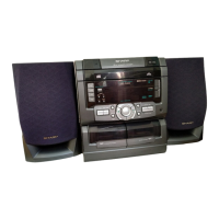
Identification and labeling of all major parts and controls on the unit and remote.
Step-by-step guide to setting the unit's clock display.
Procedure for resetting the unit's microcomputer, typically for memory clearance.
Important cautions and a step-by-step guide for disassembling the unit.
Detailed steps for removing and reinstalling key components within the CD mechanism.
Procedures for adjusting torque, tape speed, and tuner alignment.
Instructions for entering and using the CD test mode for diagnostics.
Details on automatic adjustment functions within the CD section.
Explanation of Dolby Pro Logic modes and their corresponding output states.
How to receive FM stations using the RDS service.
Description of RDS information display and PTY codes.
Overview of RDS features and differences from previous models.
Summary of how the RDS EON feature operates.
Notes explaining symbols and conventions used in schematic diagrams.
Identification of common transistor and LED types used in the unit.
First part of the system block diagram illustrating key functional blocks.
Second part of the system block diagram detailing signal flow.
Third part of the system block diagram showing power and peripheral connections.
Detailed schematic diagram of the CD servo and motor control circuits.
Troubleshooting steps for when the CD does not function or the turntable fails.
Troubleshooting for CD tray operation and function key issues.
Checks for ensuring CD playback keys are functioning correctly.
Troubleshooting steps for playback issues and tracking system checks.
Procedures for checking the CD spin system and VCO-PLL circuit.
Steps to diagnose and resolve issues with audio output.
Detailed pin functions for the IC2 Servo/Signal Control IC.
Detailed pin functions for the IC1 Servo Amplifier IC.
Detailed pin functions for the IC201 System Microcomputer IC.
Detailed pin functions for the IC601 Audio Processor IC.
Block diagram illustrating the functionality of the IC501 Dolby Pro Logic Decoder.
Block diagram for the IC3 driver IC used in the FL display.
Information on models covered and general notes regarding service manual corrections.
Details on printing errors and corrections in the parts list.
Instructions and information for ordering replacement parts.
Explanation of codes used for capacitors and resistors.
List of integrated circuits, transistors, and diodes with part numbers.
List of filters, coils, resistors, and vibrators with part numbers.
Comprehensive list of capacitors with part codes and specifications.
Comprehensive list of resistors with part codes and specifications.
List of replacement parts for CD mechanism and cabinet components.
Instructions and list of packing materials for units and speakers.
| Brand | Sharp |
|---|---|
| Model | CD-C471H |
| Category | Stereo System |
| Language | English |