FOR A COMPLETE DESCRIPTION OF THE OPERATION OF THIS UNIT,
PLEASE REFER TO THE OPERATION MANUAL.
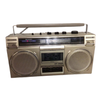
NAMES OF PARTS
1. Built-in Microphone (L-ch)
2. Power Indicator
3. FM Stereo indicator
4. Band Selector
5. Function Selector
6. Volume Control
7. Tone Control
8. Fine Tuning
9. Tuning Control
10. FM/SW Telescopic Rod Antenna
11. Built-in Microphone (R-ch)
12. Headphones Jack
13. AC Power Supply Socket
‘1
1.
14. Cassette Holder
:
,‘i
-’
15. Record Button
16. Rewind Button
‘-
17. Playback Button
18. Fast-forward Button
19. Stop Button
20. Eject Button
21. Beat Cancel Switch
22. External Microphone Jacks
23. Battery Compartment Lid
Figure 2-l
Figure 2-2
VOLTAGE SELECTION
Before operating the unit on mains, check the preset voltage.
If
the voltage is different from your local voltage, adjust the
voltage as follows: Slide the AC power supply socket cover
by a little loosing one screw to the visible indication of the side
of your local voltage. See Figure 2-3.
c
7
PHONES
’
0
Figure 2-3
-2-