Do you have a question about the Sharp GF-8H and is the answer not in the manual?
Avoid exposing the unit to extreme temperatures, both hot and cold, to prevent damage.
Protect the unit from moisture, rain, and vapor to prevent circuitry damage.
Do not expose the unit to dusty environments for extended periods.
Avoid applying organic solvents or insecticides to the unit's surface.
Do not apply oil to any part of the unit.
Grasp the plug, not the cord, when disconnecting the AC supply.
Do not remove covers; internal components pose a severe shock risk.
Collapse the telescopic aerial before moving the unit to prevent damage.
Do not store cassettes near strong magnetic fields to prevent recording degradation.
Avoid storing cassettes in hot, humid, or dusty environments.
Controls battery status indication and dial illumination.
Adjusts the output level of the right channel speaker.
Adjusts the output level of the left channel speaker.
Controls the microphone input level via the MIX MIC socket.
Adjusts treble content of audio reproduction.
Selects the reproduction mode: MONO, STEREO, or ST-WIDE.
Selects tape type (METAL or NORMAL) for recording/playback.
Slot for inserting cassette; playback starts automatically when loaded.
Starts recording automatically when cassette is inserted with key pressed.
Winds tape in reverse; also skips programs in reverse.
Winds tape forward at high speed; also skips programs forward.
Interrupts playback or recording; tape stops and resumes.
Cancels modes and ejects cassette; unit may turn off if in /TAPE position.
Turns unit on for radio or tape deck operation.
Activates or deactivates the Automatic Station Programme Search System.
Selects the broadcast band for reception: FM, MW, or LW.
Adjusts reception sensitivity and number of receivable stations.
Manually stores station frequencies for quick recall.
Scans stations upwards or advances minute digit of the clock display.
Stops advancing/reversing of displayed numbers or stops scanning.
Scans stations downwards or advances hour digit of the clock display.
Built-in microphone for the right channel.
Manually inputs broadcast frequency into microprocessor.
Adjusts built-in clock and starts timing from an adjusted time.
Selects display between frequency and time.
Activates the Automatic Station Programme Memory system.
Displays time, frequency, preset station number, and APSS function.
Tracks tape position and allows resetting the counter to zero.
Illuminates when a broadcast station is tuned.
Illuminates when APSS is searching for a programme.
Illuminates when the unit is in recording mode.
Illuminates when FM broadcast is stereophonic.
Illuminates when the unit is powered on or tape deck is operating.
Displays input/output levels and battery condition.
Built-in microphone for the left channel.
Sockets for connecting external microphones with 3.5mm plugs.
Mixes microphone input with other audio sources.
Reduces interference for MW/LW broadcasts.
For listening to audio output via stereo headphones.
For connecting external audio equipment like amplifiers.
For connecting AC or car battery adapters for power.
Extendable aerial for FM reception.
Compartment for main and microprocessor batteries.
Details the process of installing batteries in the unit.
Instructions for installing microprocessor batteries before main batteries.
Disconnects AC adaptor from the unit's DC input socket.
Removes the main battery compartment cover.
Verifies microprocessor batteries are installed.
Installs six batteries into the main compartment.
Replaces the battery compartment cover.
Replace microprocessor batteries when display is weak or absent.
Disconnects AC adaptor from the DC 9V input socket.
Sets POWER switch and unloads cassette.
Removes main batteries if they are installed.
Removes depleted microprocessor batteries.
Installs new batteries into the microprocessor compartment.
Resets clock time and radio presets.
Battery check indicates effective battery life.
Disconnects AC adaptor from the DC 9V terminal.
Turns the POWER switch to ON position.
Sets both VOLUME controls to MIN position.
VU/BATTERY meter displays battery voltage levels based on operation mode.
Sets TAPE SELECTOR based on tape type.
Engages BATTERY/LIGHT switch.
Explains battery voltage indication via LEDs.
Explains AC adaptor usage for unit operation.
Details the procedure for adjusting the voltage selector.
Verifies microprocessor batteries are installed.
Sets POWER switch to /TAPE position.
Connects AC adaptor output lead to the DC 9V terminal.
Connects AC adaptor to the AC supply socket.
Disconnects AC supply plug when not in use or on battery power.
Explains operation using a 12V vehicle battery via AD-114N adaptor.
Verifies microprocessor batteries are installed.
Connects AD-114N connector to the unit's DC 9V terminal.
Connects the other end of the adaptor to the vehicle's cigarette lighter socket.
Describes the unit's built-in quartz crystal clock and its display.
Pushes the CLOCK ADJUST button to display time and make it flash.
Verifies correct present time using external sources.
Sets the correct time using UP/MINUTE or DOWN/HOUR switches.
Sets time ahead and waits for radio time signal to finalize.
Displays current time when POWER switch is in /TAPE position.
Explains how to switch between frequency and time display.
Provides general information on radio tuning methods.
Stores and recalls desired stations using memory functions.
Explains two methods for memorizing station frequencies.
Memorizes frequencies automatically using ASPM system.
Memorizes frequencies manually using UP/DOWN switches.
Stored data is retained until microprocessor batteries are removed.
Notes that ASPM overwrites previous memory entries.
Describes ASPM's function to memorize station frequencies automatically.
Explains the ASPM system's operation with microprocessor.
Notes that ASPM overwrites previous memory entries.
Turns the unit ON to begin memory input.
Selects the desired band (MW, LW, or FM) for input.
Extends telescopic aerial for optimal FM reception.
Adjusts reception sensitivity (LOCAL/DX) for optimal tuning.
Activates automatic scanning and memory storage.
Explains the automatic scanning and numbering process for memorization.
Explains scanning stop conditions and manual band limit entry.
Describes how station crowding affects scanning and how to adjust sensitivity.
Provides instructions for manual station memorization if automatic fails.
Allows manual entry of station frequencies using numbered buttons.
Refers to previous steps for manual memory input.
Instructions for searching higher frequency stations.
Explains what happens when a station is tuned during scanning and how to memorize it.
Describes automatic repetition of scanning at band limits.
Explains how to change memorized station frequencies.
Prepares for changing memorized stations by tuning desired ones.
Selects memory slot and desired number button to change.
Instructions for recalling memorized stations.
Turns the unit ON to recall stations.
Guides selection of cassette tape type for optimal sound quality.
Emphasizes tape quality's impact on sound reproduction.
Advises against using C-120 cassettes due to potential issues.
Important notes before loading a cassette.
Checks cassette for loose tape winding.
Explains how to view spools and tighten tape.
Selects memorized station number to recall it.
Indicates FM stereo reception status.
Adjusts telescopic aerial for optimal FM reception.
Orients unit for optimal MW/LW reception.
Adjusts volume for balanced output from speakers.
Adjusts tone control for desired audio quality.
Prepares unit for radio reception; refers to Radio Operation section.
Checks battery condition before recording.
Advises using AC adaptor for long recordings to maintain battery voltage.
Selects tape type (NORMAL or METAL) for recording.
Presses the PAUSE key to prepare for recording.
Starts recording by pressing RECORD key and loading cassette.
Explains leader tape usage and initial tape run for recording.
Explains ALC circuit's control of input signal strength and VU indicator.
Reduces beat interference during MW/LW broadcasts.
Informs about reversed channel inputs during playback.
Disconnects jacks from external input sockets.
Positions the unit relative to the sound source for optimal recording.
Sets POWER switch to /TAPE position.
Explains that recorded tapes are erased during new recordings.
Allows erasing tapes without making a new recording.
Disconnects jacks from the AMP socket.
Connects erasing plug to MIC socket for tape erasure.
Inserts cassette and presses RECORD key to erase tape.
Explains how to reset the tape counter and use it for reference.
Details using the tape counter to locate recorded items.
Rewinds the tape to the beginning.
Sets counter to 000 and fast winds to find a specific number.
Describes tape searching without using APSS.
Explains the primary uses of the fast forward/rewind keys.
Sets APSS switch to OFF to disable it.
Inserts cassette and starts playback.
Uses FAST FORWARD or REWIND keys for rapid tape winding.
Interrupts fast winding/rewind and resumes playback.
Notes that most pre-recorded tapes are suitable for APSS.
Explains the need to create programme item gaps for APSS.
Notes that editing is usually not needed for records.
Uses PAUSE key at item end to create a gap.
Connects erasing plug to MIC socket for editing.
Sets POWER switch to /TAPE position.
Presses PAUSE key to create a gap.
Releases PAUSE key and advances tape for 4 seconds.
Presses PAUSE again to complete gap editing.
Removes the erasing plug from the MIC socket.
Presses PAUSE again to start recording the next item.
Summarizes steps for editing recording gaps for APSS.
Sets POWER switch to /TAPE position for playback.
Adjusts volume slightly to increase sound level.
Selects tape type (NORMAL or METAL) for playback.
Inserts cassette; playback starts automatically when fully inserted.
Adjusts volume, tone, and mode settings to personal preference.
Uses fast forward, rewind, or APSS for rapid tape movement.
Informs about reversed channel inputs during playback.
Disconnects jacks from external input sockets.
Positions the unit relative to the sound source for optimal recording.
Sets POWER switch to /TAPE position.
Refers to built-in radio recording steps for microphone recording.
States that monitoring recording is not possible.
Introduces the Automatic Programme Search System (APSS).
Explains the purpose and development of the APSS system.
Describes how Forward APSS finds the next programme item.
Describes how Reverse APSS finds the desired programme item.
Guides on preparing tapes for correct APSS operation.
Notes the requirement for 3-second intervals between programme items for APSS.
Turns the APSS switch ON.
Inserts cassette and starts playback.
Presses the FAST FORWARD key.
Explains APSS sensor scanning and indicator function.
Describes automatic playback after reaching a space between items.
Explains how to advance to subsequent programme items.
Interrupts APSS operation before gap is reached.
Outlines instructions for finding the beginning of a programme item.
Turns the APSS switch ON.
Inserts cassette and starts playback.
Presses the REWIND key.
Explains APSS sensor scanning and indicator function.
Describes automatic playback after reaching a space between items in reverse.
Explains how to search for preceding programme items.
Interrupts APSS operation before gap is reached.
Explains potential APSS skips if activated late in an item.
Suggests using PAUSE before APSS to ensure stopping at the correct space.
Lists tape recording types that may cause APSS issues.
Notes issues with low-level recordings.
Notes issues with short gaps between items.
Notes issues with noisy tapes.
Explains potential APSS failures with problematic tapes.
Describes tape searching without using APSS.
Explains the primary uses of the fast forward/rewind keys.
Sets APSS switch to OFF to disable it.
Inserts cassette and starts playback.
Uses FAST FORWARD or REWIND keys for rapid tape winding.
Interrupts fast winding/rewind and resumes playback.
Notes that most pre-recorded tapes are suitable for APSS.
Explains the need to create programme item gaps for APSS.
Notes that editing is usually not needed for records.
Uses PAUSE key at item end to create a gap.
Connects erasing plug to MIC socket for editing.
Sets POWER switch to /TAPE position.
Presses PAUSE key to create a gap.
Releases PAUSE key and advances tape for 4 seconds.
Presses PAUSE again to complete gap editing.
Removes the erasing plug from the MIC socket.
Presses PAUSE again to start recording the next item.
Summarizes steps for editing recording gaps for APSS.
Explains that recorded tapes are erased during new recordings.
Allows erasing tapes without making a new recording.
Disconnects jacks from the AMP socket.
Connects erasing plug to MIC socket for tape erasure.
Inserts cassette and presses RECORD key to erase tape.
Explains how to reset the tape counter and use it for reference.
Details using the tape counter to locate recorded items.
Rewinds the tape to the beginning.
Sets counter to 000 and fast winds to find a specific number.
Describes the automatic shut-off system for radio and audio circuits.
Notes that this function works during fast forward, rewind, or play.
Mentions the system can be used as a timer.
Guide for listening to tape while sleeping.
Starts the playback process.
Sets POWER switch to /TAPE position.
Explains that tape running time varies by cassette type.
Unit automatically turns off when cassette reaches tape end.
Instructions for using headphones with the unit.
Recommends stereo headphones for noisy environments.
Instructs to plug headphones into the PHONES socket.
Recommends specific SHARP headphone models.
Instructions for connecting and using external speakers.
States the unit can power external speakers.
Specifies impedance requirements for external speakers.
Explains internal speakers are disabled when external speakers are connected.
Advises against setting Mode Selector to ST. WIDE.
Instructions for stereo microphone recording.
Details microphone preparation and types.
Connects microphones to EXT MIC sockets.
Illustrates microphone placement.
Instructions for mono microphone recording.
Recommends stereo headphones for monitoring.
Explains how the unit mixes microphone output with other sources.
Specifies requirements for the mixing microphone.
Describes monaural recording/playback of mixing microphone input.
Explains mixed playback of tape and external mic, but not recording.
Sets POWER switch to /TAPE position.
Connects mixing microphone to the MIX MIC socket.
Starts playback and refers to playing instructions.
Adjusts tape output level for balanced playback with mic input.
Adjusts microphone input level.
Advises on troubleshooting howling by moving mic or reducing volume.
Refers to previous steps for mixed recording setup.
Prepares unit for radio reception.
Adjusts microphone input level.
Adjusts radio output level.
Outlines steps for mixed recording process.
States that the unit requires no additional lubrication.
Provides instructions for cleaning the unit's cabinet.
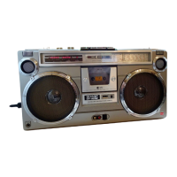
General overview of the unit's features and capabilities.
Details the power sources for the unit.
Specifies the output power of the unit.
Describes the speaker type.
Lists the semiconductor components used.
Provides the physical dimensions of the unit.
States the weight of the unit.
Technical specifications related to the tape recorder function.
Specifies the type of cassette tape used.
Lists the frequency response characteristics.
States the Signal-to-Noise ratio.
Details input impedance values.
Mentions the DIN input specification.
Specifies the loaded impedance.
Technical specifications related to the radio tuner function.
Lists the frequency range for radio reception.
Manufacturer's note regarding specifications and design changes.
| Manufacturer | Sharp |
|---|---|
| Country | Japan |
| Power Supply | AC 110-120V, 220-240V, 50/60Hz |
| Batteries | 8 x D |
| Tape Mechanism | Auto Stop |
| Features | AM/FM radio |
| Speakers | 2 x built-in speakers |