EasyManua.ls Logo

Sharp GF-9292X User Manual

Sharp GF-9292X
5 pages
To Next Page IconTo Next Page
Page #1 background imageLoading...
Page #1 background image
w
Service
Manual
The model
GF-9292X
same
as
the
former
GF
(1)
The meter
is
of
LED
indication.
(2) The
front
design
is
different
from
that
of the
GF-9191X.
(3)
“AM”
indication of the radio
band
selector
is
different
from the
corresponding one
(“MW”)
of that of the
GF-9191X.
As
for
the
items
“Description of
APSS”,
“Mechanical Adjustment”,
“Electrical Measurement”
and
“General Alignment Instruction”. they
are
all
omitted
from
the explanations of
this
Service
Manual
and
there-
fore refer to the already
issued
“GF-9191X
Service
Manual” to
see
the
details of them.
SPECIFICATIONS
GENERAL
Type:
Power source:
Power consumption:
Speaker:
Power output:
Semiconductors:
Dimentions:
Weight:
Input terminals:
Outout terminals:
Auto Program Search System
MODEL
GF-9292X
In
the
interests
of
user-safety
the
set
should
be
restored
to
its
original condition
and
only
parts
identical to
those
specified
be
used.
Portable stereophonic cassette tape
recorder with built-in AM/SW,/SWZ/
FM
4-band
radio
AC 110/220/24OV, 50/60 Hz
DC 15V (Ten
UM/SUM-1
, R20, D
size batteries or External DC supply)
35
w
16 cm (Woofer) x 2,
5 cm (Tweeter)
x
2
Dynamicpower20W(10W+10W)
8-IC (Integrated Circuit), 34-transistor
and 44-diode (13-Light Emitting Diode)
516mm(W)
x 115mmiD) x 271mm(H)
[20-5/16(W)x4-1/2(D)x10-11/16(H)1
6.5 kg (14.3
Ibs.)
(without batteries)
1 EXT.
MIC.
600 ohms
(JlOl-A,
JlOl-B)
2 Mixing mic. 600 ohms
(J401)
3 Remote control
(JIOI-G)
4 EXT. DC power
(JSOI
)
5
AC input power
(SO901)
6
REC/PB
DIN socket, 2.5
mV/lO
K
ohms (SO1 01)
7 FM EXT. antenna
(TBI)
8 PHONO
(J103-A,
J103-B)
1 EXT. speaker, 4
-
8 ohms
(JlOl-E,
JlOl-F)
2 PHONES, 8
-
25 ohms
(J603)
3
REC/PB
DIN socket, 0.7V/50K ohms
(s0101)
4 Line out, 0.7 V/50
K
ohms
(JlOl-C,
JIOI-D)
TAPE RECORDER SECTION
Type:
4-track stereo cassette tape recorder
Tape:
Philips type compact cassette tape
Tape speed:
4.8 cm/set.
Recording system:
AC bias
Erasing system:
AC erasing
Recording time:
60 minutes (with C-60 tape)
Fast forward or
rewind time:
120
sec. (with C-60 tape)
Frequency response: 40
-
15,000 Hz
(CrOz
tape)
40
-
12,000 Hz (Normal tape)
Wow and flutter:
0.09%
(WR
MS)
SIN ratio:
50
dB
RADIO SECTION
Frequency
range:
AM 525
-
1,605
kHz
SW,
2.3
-
7.3 MHz
SW2
7.3
-
22 MHz
FM
87.6
-
108
MHz
Intermediate
frequency:
AM/SWI/SW2
455
kHz
FM
10.7
MHz
4-band
superheterodyne system
AM/SW, ferrite core bar antenna
SW,
/SW,/FM
telescopic antenna
FM EXT. antenna
Circuit system:
Antenna:
Question and Answer IconNeed help?

Do you have a question about the Sharp GF-9292X and is the answer not in the manual?

Sharp GF-9292X Specifications

General IconGeneral
TypeBoombox
BrandSharp
ModelGF-9292X
CountryJapan
SpeakersYes
TunerAM/FM
Speaker Configuration2-way
Frequency Response40 Hz - 16 kHz
InputsMicrophone
OutputsHeadphones
Tape deckSingle

Summary

SPECIFICATIONS

GENERAL

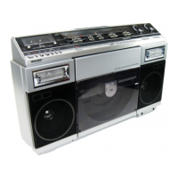
Details about the unit's type, power, speaker, output, semiconductors, dimensions, weight, and inputs/outputs.

TAPE RECORDER SECTION

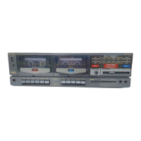
Specifications for the tape recording functionality, including type, speed, bias, erasing, and frequency response.

RADIO SECTION

Specifications for the radio tuner, covering frequency ranges, intermediate frequencies, circuit system, and antenna types.

NAMES OF PARTS

Front Panel Controls and Indicators

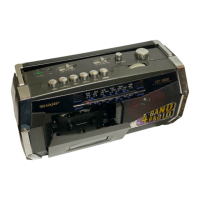
Identifies front panel components like meters, microphones, headphone jack, and various operational keys and controls.

Top Panel Controls

Details controls located on the top surface, including loudness, meter/dial switches, mode selectors, and tape selectors.

Front Panel Controls (Lower Section)

Identifies lower front panel controls such as record level, bass, treble, volume, fader, and APSS/stop keys.

Rear and Side Panel Connectors

Identifies external connection terminals and power inputs found on the rear and side of the unit.

DISASSEMBLY

FRONT CABINET REMOVAL

Step-by-step instructions for removing the front cabinet and disconnecting speaker tips.

OPERATION PANEL REMOVAL

Instructions for removing the operation panel after the front cabinet is detached.

MECHANISM BLOCK REMOVAL

Procedure to disconnect sockets and remove the mechanism block.

CHASSIS (P.W.B.) REMOVAL

Steps to remove the main chassis (Printed Wiring Board) after other parts are detached.

DIAL SCALE PLATE REMOVAL

Steps to remove the dial scale plate after the operation panel is removed.

PHONO JACK PLATE REMOVAL

Instructions for removing the phono jack plate after the mechanism block is removed.

LEVEL AND SENSITIVITY ADJUSTMENT OF VU METER

VU Meter Adjustment Procedure

Detailed steps for connecting test equipment and adjusting controls for accurate VU meter readings.

Switch and Control Settings

Lists switch positions and VR control settings required for the adjustment procedure.

ALIGNMENT POINTS

Alignment Diagram and Test Points

Diagram showing alignment points, test points (TP), and component locations for calibration.
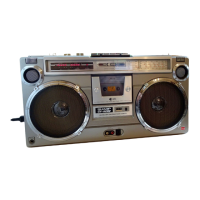
Related product manuals