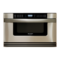
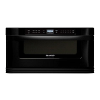
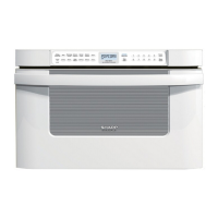
21
KB-6021MS
KB-6021MK
KB-6021MW
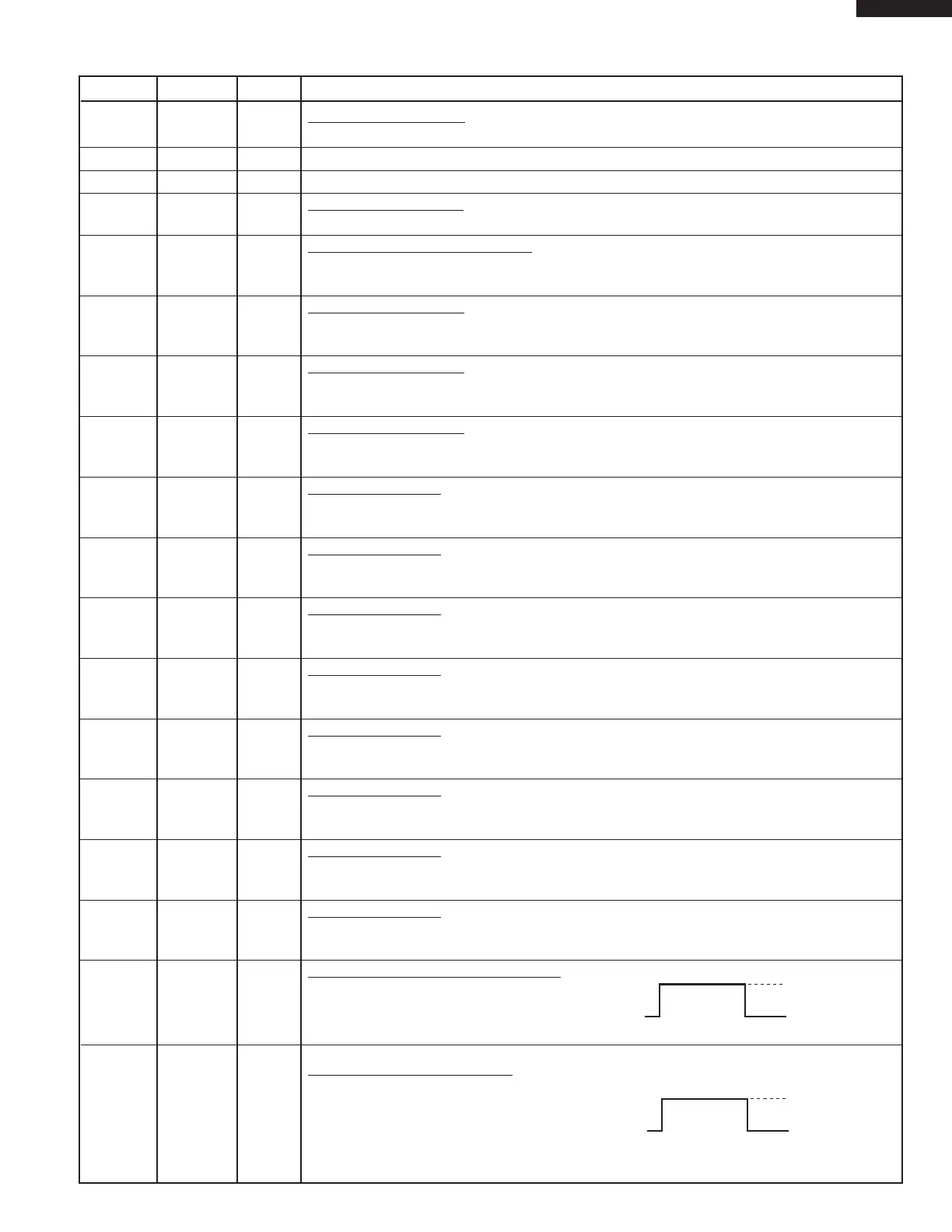
27 COM0 OUT Common data signal.
Connected to LCD signal C4.
28 VL3 IN Connected VC (+5V).
29 - 31 P27- P25 OUT Terminal not used.
32 SEG20 OUT
Segment data signal.
Connected to LCD segment S24.
33 P23 IN Signal coming from touch key.
When any one of J-4 line keys on key matrix is touched, a corresponding signal from P10-
P17 will be input into P23. When no key is touched, the signal is held at "L" level.
34 P22 IN
Signal similar to P23.
When any one of J-3 line keys on key matrix is touched, a corresponding signal will be
input into P22.
35 P21 IN Signal similar to P23.
When any one of J-2 line keys on key matrix is touched, a corresponding signal will be
input into P21.
36 P20 IN Signal similar to P23.
When any one of J-1 line keys on key matrix is touched, a corresponding signal will be
input into P20.
37 P17 OUT Key strobe signal.
Signal applied to touch-key section. A pulse signal is input to P20 - P23 terminal while
one of J-12 line key on matrix is touched.
38 P16 OUT Key strobe signal.
Signal applied to touch-key section. A pulse signal is input to P20 - P23 terminal while
one of J-11 line key on matrix is touched.
39 P15 OUT Key strobe signal.
Signal applied to touch-key section. A pulse signal is input to P20 - P23 terminal while
one of J-10 line key on matrix is touched.
40 P14 OUT Key strobe signal.
Signal applied to touch-key section. A pulse signal is input to P20 - P23 terminal while
one of J-9 line key on matrix is touched.
41 P13 OUT Key strobe signal.
Signal applied to touch-key section. A pulse signal is input to P20 - P23 terminal while
one of J-8 line key on matrix is touched.
42 P12 OUT Key strobe signal.
Signal applied to touch-key section. A pulse signal is input to P20 - P23 terminal while
one of J-7 line key on matrix is touched.
43 P11 OUT Key strobe signal.
Signal applied to touch-key section. A pulse signal is input to P20 - P23 terminal while
one of J-6 line key on matrix is touched.
44 P10 OUT Key strobe signal.
Signal applied to touch-key section. A pulse signal is input to P20 - P23 terminal while
one of J-5 line key on matrix is touched.
45 P07 OUT Fan motor (Drawer) driving signal.
To turn on and off relay(RY4).
“H” level: During fan motor ON.
“L” level: During fan motor OFF.
46 P06 OUT Stirrer motor driving signal.
To turn on and off relay(RY3).
“H” level: During fan motor ON.
“L” level: During fan motor OFF.
Pin No. Signal I/O Description