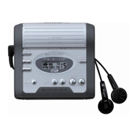
EasyManua.ls Logo

Sharp MD-MT270HS/BK - User Manual

Sharp MD-MT270HS/BK
56 pages
To Next Page IconTo Next Page
Loading...
MD-MT270H
SERVICE MANUAL
SHARP CORPORATION
No. SX299MDMT270H
This document has been published to be used
for after sales service only.
The contents are subject to change without notice.
PORTABLE MINIDISC RECORDER
Page
SAFETY PRECAUTION FOR SERVICE MANUAL ............................................................................................................... 2
SPECIFICATIONS ................................................................................................................................................................. 3
NAMES OF PARTS ............................................................................................................................................................... 4
DISASSEMBLY...................................................................................................................................................................... 5
REMOVING AND REINSTALLING THE MAIN PARTS......................................................................................................... 6
ADJUSTMENT ........................................................................................................................................................................ 7
MD ERROR MESSAGE DISPLAY CONTENT LIST ........................................................................................................... 21
NOTES ON SCHEMATIC DIAGRAM .................................................................................................................................. 22
TYPES OF TRANSISTOR AND DIODE .............................................................................................................................. 22
BLOCK DIAGRAM ............................................................................................................................................................... 23
SCHEMATIC DIAGRAM ...................................................................................................................................................... 24
WIRING SIDE OF P.W.BOARD........................................................................................................................................... 32
VOLTAGE ............................................................................................................................................................................ 36
WAVEFORMS OF MD CIRCUIT ......................................................................................................................................... 37
TROUBLESHOOTING ......................................................................................................................................................... 38
FUNCTION TABLE OF IC.................................................................................................................................................... 41
PARTS GUIDE/EXPLODED VIEW
PACKING OF METHOD (FOR U.K. ONLY)
CONTENTS
In the interests of user-safety the set should be restored to its
original condition and only parts identical to those specified be
used.
MODEL
MD-MT270H(S)/(BK)

Questions and Answers:

Sharp MD-MT270HS/BK Specifications

General IconGeneral
BrandSharp
ModelMD-MT270HS/BK
CategoryMeasuring Instruments
LanguageEnglish

Summary

SAFETY PRECAUTION FOR SERVICE MANUAL

Laser Pickup Servicing Precautions

Guidelines for safe replacement and servicing of the laser pickup.

Laser Diode Properties

Details on laser diode material, wavelength, and pulse characteristics.

SPECIFICATIONS

Power and Performance Specifications

Details on power source, consumption, output, dimensions, and battery life.

Audio and Recording Specifications

Covers audio channels, frequency response, sampling, and error correction.

NAMES OF PARTS

Main Unit and Display Panel Components

Identification of buttons, indicators, and parts on the main unit and display.

DISASSEMBLY

Pre-Disassembly Cautions and Steps

Safety and handling notes before disassembling, followed by disassembly steps.

REMOVING AND REINSTALLING THE MAIN PARTS

Mechanism Component Removal Procedures

Step-by-step guides for removing magnetic head, motors, and optical pickup.

ADJUSTMENT

Test Mode Entry and Operation Overview

Instructions for entering test mode and overview of available adjustment modes.

ADJUSTMENT PROCEDURES AND TEST MODES

Test Mode Operations (AUTO1, AUTO2, TEST-PLAY)

Detailed operation for AUTO1, AUTO2, and TEST-PLAY adjustment modes.

EEPROM Writing and Temperature Setting

Procedure for EEPROM replacement, initial value writing, and temperature reference setting.

TEST MODE CHANGE CHART

Test Mode Menu Navigation and Pre-adjustment

Chart for navigating test modes and details on preautomatic adjustment.

ADVANCED TEST MODE FUNCTIONS

ATT Auto Adjustment and Continuous Playback

Procedures for ATT auto adjustment and continuous playback.

Record, Error Display, and EEPROM Settings

Details on continuous record, error display, and EEPROM setting menus.

TEST MODE SETTING MENUS

Focus, Spin, Tracking, and Sled Settings

Procedures for adjusting Focus, Spin, Tracking, and Sled parameters.

Temp, Bass, Control, and Adjustment Settings

Guides for Temp, Bass, Control, and Adjustment settings.

MD ERROR MESSAGE DISPLAY CONTENT LIST

Error Code Reference

List of error messages, their content, codes, and remarks.

NOTES ON SCHEMATIC DIAGRAM

Component Notation and Safety Notes

Explanation of resistor/capacitor codes and safety markings.

SYSTEM BLOCK DIAGRAM

Overall System Architecture

Diagram showing the main components and their interconnections.

SCHEMATIC DIAGRAM (1;8)

Circuit Connections - Part 1

Detailed schematic of circuit connections for the first section.

WIRING SIDE OF P.W.BOARD (1;4)

Main PWB-A Wiring Layout

Diagram illustrating the wiring on the main PWB-A (bottom view).

VOLTAGE MEASUREMENT POINTS

IC Pin Voltage Reference

Table of voltage readings for various IC pins.

WAVEFORMS OF MD CIRCUIT

Oscilloscope Waveform Analysis Guide

Reference waveforms for troubleshooting and diagnosis.

TROUBLESHOOTING GUIDE

Playback and Display Fault Diagnosis

Steps for diagnosing playback failures and abnormal display issues.

TROUBLESHOOTING AUDIO AND MOTOR

Audio Circuit and Motor Operation Issues

Troubleshooting for audio playback and spindle motor problems.

TROUBLESHOOTING RECORDING;PLAYBACK

Recording and Playback Operation Faults

Steps for diagnosing issues with recording and playback operations.

FUNCTION TABLE OF IC401

IC401 Pin Functions (1;2)

Pinout and function table for the microcomputer IC401.

FUNCTION TABLE OF IC401

IC401 Pin Functions (2;2)

Continued pinout and function table for IC401 microcomputer.

IC201 ENDEC;SERVO;ATRAC DETAILS

IC201 Output Port and Settings

Details on IC201 output ports and test/LDCNT settings.

IC601 PWM;MOTOR DRIVER DETAILS

IC601 Pin Functions (1;2)

Pinout and function descriptions for IC601 PWM/Motor Driver.

IC601 PWM;MOTOR DRIVER DETAILS

IC601 Pin Functions (2;2)

Continued pinout and function descriptions for IC601.

IC202 16 M BIT D-RAM DETAILS

IC202 Pin Functions

Pinout and function descriptions for IC202 D-RAM.

PARTS GUIDE

Ordering Replacement Parts and Codes

Information on ordering parts and explanation of capacitor/resistor codes.

MD MECHANISM EXPLODED VIEW

Mechanism Component Layout Diagram

Exploded view showing the arrangement of MD mechanism parts.

CABINET EXPLODED VIEW

Cabinet Component Layout Diagram

Exploded view showing the arrangement of cabinet parts.

PACKING METHOD (U.K. ONLY)

Packing Contents and Switch Settings

List of packing items and instructions for switch/knob settings.

Related product manuals