MX3500N SIMULATION 7 – 98
<Set range and default value of each setup>
50-2
Purpose
Adjustment
Function (Purpose)
Used to adjust the copy image position on
print paper in the copy mode and to adjust
the void area (image loss). (Simple adjust-
ment)
(Similar to SIM50-01. This simulation pro-
vides the simpler method.)
Section
–
Item
Image quality (Image position)
Operation/Procedure
1) In advance to this adjustment, execute the magnification ratio
adjustment in the sub scanning direction (SIM48-01).
2) Select "TRAY"and set 0 to L1 and L2.
* L1 and L2 are changed to 0, the following adjustment values
are automatically set.
RRCA adjustment value: 50
RRCB adjustment value: 90
(Reference value 50 + paper lead 49 (4.9mm))
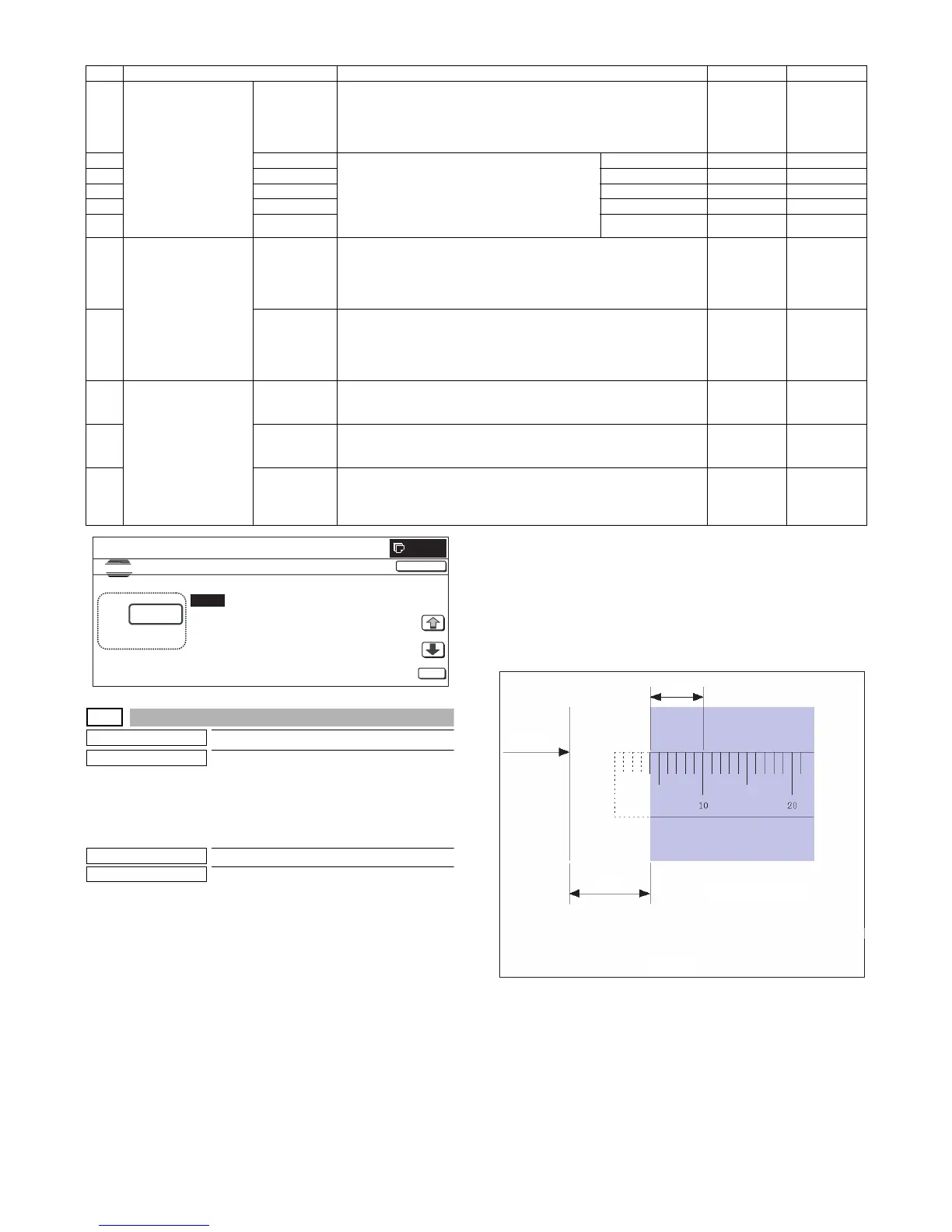
3) Place a ruler along the left edge of the document table, and
make a black copy in 400%.
4) Measure the distances L1 and L2 on the copied image in the
unit of 0.1mm, and multiple the distance values with 10, and
enter the obtained values. (Be sure to enter L1 and L2
together.)
• L1: Distance between the copy image lead edge position
and the scale of 10mm.
• L2: Distance between the paper lead edge and the copy
image lead edge position.
5) When [EXECUTE] button is pressed, the current entered value
is saved to EEPROM and RAM.
6) Make a black copy in 100%, and adjust the rear edge void.
* When [CLOSE] button is pressed, the display is shifted to the
copy basic screen of simulation.
* Copying can be performed also by pressing [COLOR]/[BLACK]
key.
Item Display item Description Set range Default value
A Lead edge adjustment
value
RRCA Document lead edge reference position (OC)
The timing from start of document scan to recognition of the image lead
edge is adjusted. (0.1mm/step)
* The smaller the set value is, the faster the timing is. The greater the set
value is, the slower the timing is.
0 to 99 50
B RRCB-CS12 Resist motor ON timing adjustment
The timing to turn ON the resist roller from reception
of the resist signal is adjusted. (0.1mm/step)
* The smaller the set value is, the faster the timing
is. The greater the set value is, the slower the
timing is.
Standard cassette 1 to 99 50
C RRCB-CS34 Desk 1 to 99 50
D RRCB-LCC LCC 1 to 99 50
E RRCB-MFT Manual feed 1 to 99 50
F RRCB-ADU ADU 1 to 99 50
G Image loss quantity set
value
LEAD Lead edge image loss quantity setting
The lead edge image loss quantity is specified. The difference between the
document lead edge scan start position and the document lead edge
(0.1mm/step))
* The greater the value is, the grater the image loss is.
0 to 99 30
H SIDE Side image loss quantity setting
The side image loss quantity is specified. (Document width – Document
edge scan range) / 2 (0.1mm/step)
(The rear edge image loss quantity is fixed to 0. (Without adjustment))
* The greater the value is, the greater the image loss is.
0 to 99 20
I Void amount setting DENA Print lead edge adjustment
The void quantity formed at the paper lead edge is specified. (0.1mm/step)
* The greater the value is, the greater the void is.
1 to 99 30
J DENB Sub scan direction print range adjustment
The void quantity formed at the paper rear edge is specified. (0.1mm/step)
* The greater the value is, the greater the void is.
1 to 99 20
K FRONT/REAR FRONT/REAR void amount adjustment
The void quantities formed at the right and left edges are adjusted.
(0.1mm/step)
* The greater the value is, the greater the void is.
1 to 99 20