'.
i.
•
• Adjustment
Adjust and check the following when exchanging IC7, 20,
26
(74LS123N), TR 1 and their peripherals.
When adjusting, add power voltage 5V to TP7 (+5V) and TP9
(DV)
and apply 4MHz clock (duty ratio 50%,
TTl
level)
to
TP2.
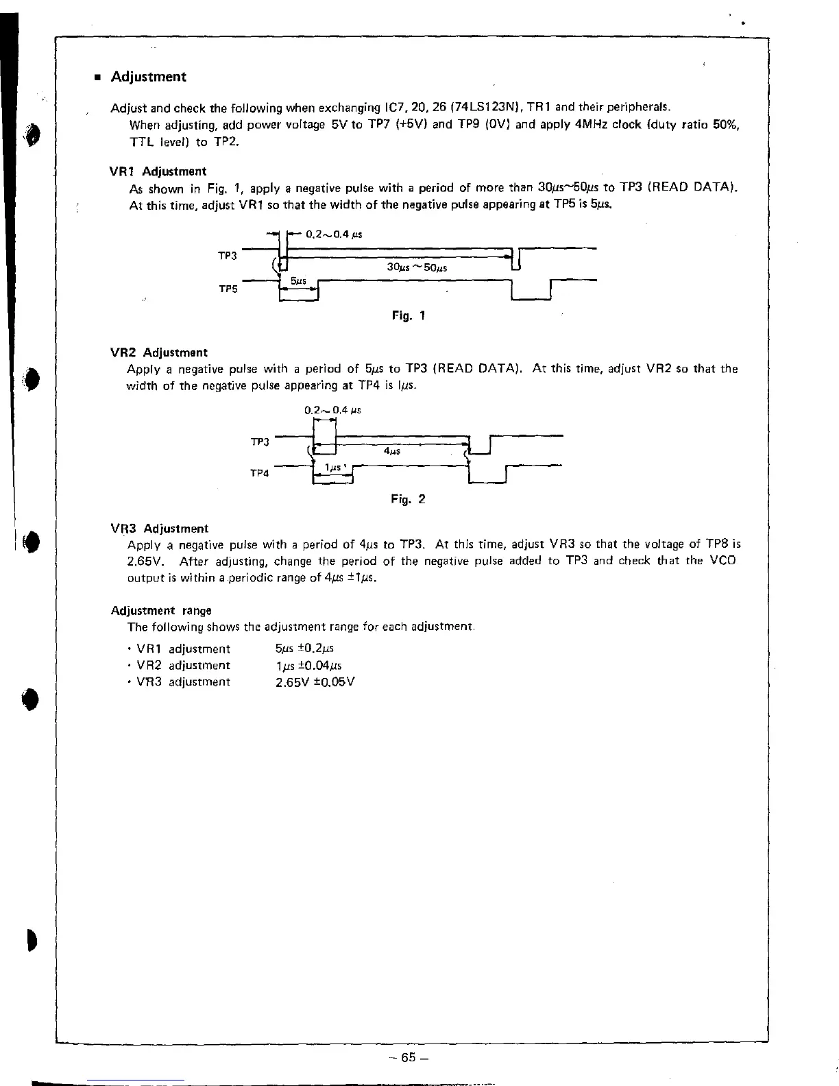
VR 1 Adjustment
As
shown
in
Fig.
1, apply a negative pulse with a period of more than 30/1s-50/1s
to
TP3 (READ DATA).
At
this time, adjust
VR1
so
that
the width
of
the negative pulse appearing
at
TP5
i.
5/1',
~
10.2-0.4#S
TP3
-{;""s
.
'U
U.
3D.us
......
50",s
TP5
#
------------------------,~
Fig. 1
VR2
Adju.tment
Apply a negative pulse with a period
of
5/1'
to
TP3 (READ DATA).
At
this time, adjust VR2
So
that
the
width
of
the
negative pulse appearing at TP4
is
IllS.
0.2.-.....
0.4
j..lS
TP3
--
---.Ml-t====;:::::======:::t
--0
4IJ.s
TP4
-
---j~1:".=':r------------_t
Fig. 2
VR3 Adjustment
Apply a negative pulse with a period
of
4/1s
to TP3. At this time, adjust VR3 so that the voltage of TP8
is
2.65V. After adjusting, change the period
of
the negative pulse added
to
TP3 and check
that
the
VCO
output
is
within a periodic range
of
4ps ±l,us.
Adjustment
range
The following shows the adjustment
range
for each adjustment.
•
VRt
adjustment
• V
R2
adjustment
• VR3 adjustment
5/15
±O.2J15
1J1s
±O.D4/15
2.65V ±O.05V
-
65-
...
-----------------
 Loading...


